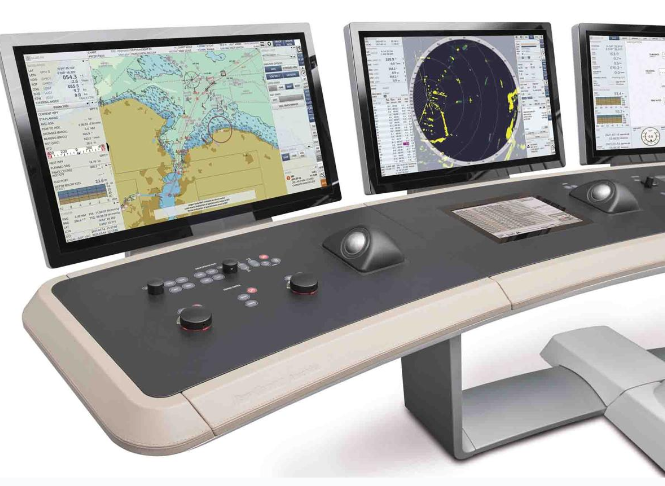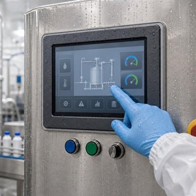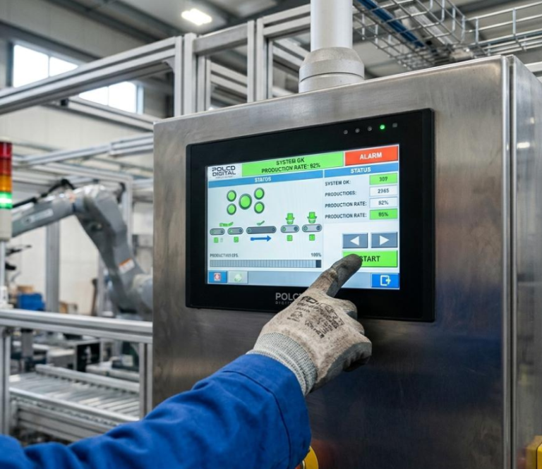
Una pantalla LCD TFT industrial debe seleccionarse desde la tarea operativa hacia afuera. Comience con lo que el usuario debe ver y tocar, luego tenga en cuenta la luz ambiental, la temperatura, la humedad, la vibración, el ruido eléctrico y la vida útil.
Este orden importa porque las especificaciones interactúan. Más salida de retroiluminación mejora la visibilidad pero añade calor. Un vidrio de cubierta más grueso puede mejorar la protección mecánica pero debilita el acoplamiento táctil capacitivo. El tratamiento antirreflejo reduce los reflejos nítidos pero puede suavizar los píxeles pequeños. El pegado óptico mejora el contraste percibido, pero cambia el costo, la reparación y el control del proceso.
La matriz de selección en esta guía compara cuatro aplicaciones comunes: control industrial, equipos médicos, HMI vehiculares y terminales exteriores. Los valores son puntos de partida de ingeniería, no límites universales de aprobación/rechazo. Los requisitos finales deben verificarse en el producto completo.
Resumen de selección rápida
- Control industrial en interiores: Comience alrededor de 400–700 nits, con tratamiento AG donde la iluminación cenital cause deslumbramiento. Priorice largas horas de operación, rendimiento táctil resistente a EMI y montaje práctico.
- Equipos médicos: Comience alrededor de 350–600 nits para interfaces clínicas generales. Defina los químicos de limpieza, el uso de guantes, los requisitos de escala de grises o color y el rol de la pantalla antes de especificar recubrimientos o pegado.
- HMI vehicular: Comience alrededor de 800–1,500 nits para ubicaciones de cabina expuestas al sol, mientras también requiere un brillo nocturno muy bajo. Valide la carga térmica, la vibración, la geometría de visión y la ubicación exacta de montaje.
- Terminal exterior: Comience alrededor de 1,000–2,500 nits dependiendo de la luz solar directa, el reflejo y la distancia de visión. Reduzca el reflejo antes de aumentar la potencia de retroiluminación, y valide la carcasa sellada bajo carga solar.
Estos rangos se superponen. Un controlador exterior protegido puede requerir menos brillo que una HMI de máquina frente a una ventana iluminada por el sol. El entorno del producto—no la etiqueta de la industria—establece el objetivo final.
1. Adapte el brillo a la luz ambiental y al presupuesto térmico
La luminancia de la pantalla se mide en candelas por metro cuadrado, comúnmente llamadas nits. Indica cuánta luz sale de la superficie medida; no indica cuánto contraste permanece después de que la luz ambiental es reflejada por el vidrio de cubierta y las interfaces ópticas internas.
300–400 nits: Condiciones interiores controladas
Este rango puede ser adecuado para equipos de laboratorio, electrónica montada en rack y terminales interiores con iluminación controlada y sin luz solar directa.
A este nivel, revise los reflejos de las luces cenitales y las ventanas. Una pantalla de 350 nits detrás de vidrio brillante sin tratamiento puede ser menos cómoda que una pantalla similar con un tratamiento superficial cuidadosamente seleccionado.
400–700 nits: Entornos industriales generales
Este es un rango de partida práctico para HMI de fábrica, instrumentos portátiles y paneles de control bajo iluminación interior típica.
Un brillo cercano al extremo superior puede ayudar donde puertas grandes, tragaluces o iluminación de tarea intensa introducen más luz ambiental. No debe reemplazar una evaluación del deslumbramiento, el ángulo de visión y la posición de la carcasa.
700–1,000 nits: Uso interior brillante y exterior protegido
Este rango se evalúa a menudo para equipos cerca de ventanas, cabinas de vehículos, terminales semi-exteriores y dispositivos usados principalmente en sombra abierta.
El tratamiento AR o AG y el pegado óptico pueden proporcionar más valor que aumentar solo el brillo del panel. Confirme el brillo a través del conjunto terminado de táctil y cubierta.
1,000–1,500 nits: Uso exterior regular o expuesto al sol
Este rango es un punto de partida de ingeniería común para HMI vehiculares, cargadores de EV, equipos de campo y terminales exteriores que enfrentan luz diurna intensa.
A este nivel, la gestión de potencia y térmica se vuelve central. Pruebe la pantalla después de que la carcasa sellada alcance su temperatura interna esperada, no solo en un banco abierto.
1,500–2,500 nits: Condiciones severas de sol directo
Un brillo muy alto puede justificarse para sol directo continuo, largas distancias de visión, grandes pérdidas ópticas o información que debe reconocerse de inmediato.
No es automáticamente la mejor solución. Un ensamblaje de 2,000 nits altamente reflectante puede rendir peor que una pantalla de menor brillo con una pila pegada y de bajo reflejo bien diseñada. Una mayor salida también aumenta la carga eléctrica, el calor y el estrés de los LED.
QIHAN enumera públicamente soluciones seleccionadas de alto brillo de hasta 1,800 nits. Los requisitos por encima de ese nivel deben tratarse como una cuestión de viabilidad específica del proyecto en lugar de una capacidad estándar asumida.
Especifique la superficie de medición
Cada requisito de brillo debe indicar uno de los siguientes:
- Luminancia del panel TFT desnudo
- Luminancia a través del panel táctil
- Luminancia en el exterior de la lente de cubierta terminada
El valor final es normalmente el más relevante para el usuario. También especifique si el número es típico o mínimo, junto con las condiciones de uniformidad, temperatura y atenuación.
2. Tratamientos superficiales AR, AG y AF
Los tratamientos superficiales resuelven problemas diferentes y no deben combinarse por defecto.
AG: Antirreflejo
El tratamiento AG difunde la luz reflejada para que un reflejo nítido de lámpara o ventana se vuelva menos definido.
Esto puede mejorar la comodidad en fábricas, vehículos y kioscos. Una neblina excesiva puede reducir la nitidez aparente y crear destellos sobre píxeles pequeños de alta densidad. Evalúe el AG con la resolución real de la pantalla y los gráficos de la interfaz.
AR: Antirreflejo
El tratamiento AR reduce el reflejo tipo espejo mediante un recubrimiento óptico o una estructura superficial.
Puede preservar mejor la claridad que una superficie AG de alta neblina. La reflectancia real depende de la longitud de onda, el ángulo, el sustrato y la pila completa. No cite un objetivo de reflexión inferior al 1% a menos que el proveedor defina el método de medición y la superficie a la que se aplica.
AF: Antihuellas
El tratamiento AF reduce las huellas visibles y puede mejorar la limpieza y la sensación táctil.
Es útil para interfaces táctiles médicas, vehiculares y públicas. El tratamiento debe verificarse en cuanto a vida útil frente a la abrasión y compatibilidad con agentes de limpieza de producción.
Una elección práctica de tratamiento
| Problema visual principal | Inicio del tratamiento | Verificación |
|---|---|---|
| Reflejos nítidos de lámparas, ventanas o cielo | AR | Medir el reflejo e inspeccionar en los ángulos esperados |
| Resplandor amplio que causa incomodidad al operador | AG equilibrado | Verificar haze, centelleo y claridad de detalles finos |
| Contacto frecuente con los dedos y manchas visibles | AF sobre una superficie compatible | Probar el ciclo de limpieza y abrasión |
| Interfaz táctil para exteriores con varios problemas | Combinación AR/AG/AF específica del proyecto | Evaluar el stack terminado, no muestras de materiales por separado |
3. Unión perimetral vs. unión óptica
Unión perimetral o unión por aire
La unión perimetral fija el panel táctil o la lente de cubierta alrededor de sus bordes, dejando un espacio de aire sobre el TFT.
Las ventajas pueden incluir menor costo, procesamiento más simple y reemplazo más fácil de capas. Las limitaciones incluyen reflexiones internas adicionales y una cavidad en la que el aire cargado de humedad puede condensarse.
Puede ser adecuada para equipos indoor controlados cuando el rendimiento óptico y el riesgo de condensación son aceptables.
Unión óptica
La unión óptica rellena el espacio con un material OCA o OCR transparente. Reducir la discontinuidad del índice de refracción puede disminuir las reflexiones internas y mejorar el contraste percibido.
También elimina la cavidad de aire interna y proporciona soporte mecánico entre las capas. Por sí sola, no hace que un recinto sea impermeable ni certifica el ensamblaje contra impactos.
La unión óptica suele ser valiosa para:
- Pantallas legibles a la luz solar
- Lentes de cubierta grandes u oscuras donde el reflejo es visible
- Pantallas de vehículos que requieren una apariencia negra integrada
- Equipos médicos expuestos a limpieza frecuente o riesgo de salpicaduras
- Pantallas sometidas a vibración o presión del usuario
No es obligatoria para todos los productos de esas categorías. El costo, la estrategia de reparación, el tamaño del módulo, el rendimiento de la unión y el riesgo de la aplicación siguen siendo importantes.
Criterios de aceptación de la unión
Definir límites para:
- Burbujas y partículas
- Alineación y posición del área activa
- Defectos en los bordes y desbordamiento de adhesivo
- Mura o marcas de presión
- Amarillamiento o haze después del envejecimiento
- Delaminación después de exposición térmica y a la humedad
- Uniformidad óptica
“Totalmente unido” describe un proceso; no define la calidad.
4. Táctil capacitivo Respuesta y robustez
El táctil capacitivo proyectado, o PCAP, detecta cambios en un campo eléctrico. La respuesta táctil depende del patrón del sensor, el controlador, el vidrio de cubierta, el adhesivo, la puesta a tierra, el ruido eléctrico y el firmware.
No especificar el tiempo de respuesta como un solo número demasiado pronto
El usuario experimenta varios retrasos:
- Intervalo de escaneo del sensor
- Filtrado del controlador y confirmación del toque
- Comunicación con el host
- Procesamiento del sistema operativo
- Respuesta de la aplicación
- Actualización del cuadro de pantalla
Un controlador rápido no puede compensar una aplicación lenta o un pipeline de pantalla lento. Definir un objetivo de interacción de extremo a extremo para la tarea real de HMI, luego asignar el presupuesto a través del sistema.
Para controles industriales, una respuesta consistente y el rechazo de toques falsos inseguros pueden importar más que la latencia reportada más corta posible.
Glove Operation
Thick cover glass and gloves both reduce capacitive coupling. Increasing sensitivity can recover the signal but may reduce tolerance to noise or water.
Specify the actual glove material, thickness and condition. A thin nitrile examination glove is different from a leather work glove or insulated winter glove.
Do not promise operation through 3–5 mm gloves or glass based on thickness alone. Validate the final sensor, controller, cover, enclosure and glove sample.
Water and Wet-Finger Behavior
Water can connect sensor channels and resemble a touch. A controller may reject droplets, accept a single wet finger, limit gestures or temporarily disable input on a flooded surface.
Define the intended behavior for rain, cleaning spray, condensation, wet fingers, flowing water and standing water. “Water tolerant” is incomplete without a test condition and expected response.
Electrical Noise
Motors, inverters, chargers, radios and switching power supplies can disturb PCAP sensing.
Frequency hopping and digital filtering may help, but hardware still matters. Review clean power, grounding, shielding, FPC routing, metal near the sensor and communication-cable length.
Final tuning should use the production-intent enclosure with the real equipment active at worst-case operating modes.
5. Vidrio de cobertura and Mechanical Durability
Cover-glass thickness is only one part of impact performance.
Chemical strengthening, material, edge quality, unsupported span, holes, mounting adhesive, enclosure stiffness and impact geometry all influence the result. A 6 mm cover can still fail if its edge is poorly supported; a thinner cover may perform well in a carefully designed assembly.
Surface-hardness values such as 6H, 7H or 9H refer to a defined test method and should not be treated as direct measures of impact resistance.
IP and IK Ratings Belong to Tested Assemblies
IEC 60529 classifies protection provided by electrical-equipment enclosures against access, solid objects and water.
IK ratings similarly apply to the tested enclosure’s resistance to external mechanical impact. A loose touch panel or cover lens cannot establish the complete equipment’s IP65, IP67 or IK10 rating.
If the product has an IP or IK target, coordinate:
- Cover-lens dimensions and unsupported area
- Gasket compression
- Bond width and adhesive
- Housing stiffness
- Cable and connector sealing
- Drainage or pressure equalization
- Test fixture and impact location
6. Application Requirements
Industrial Control and Factory HMI
The main risks are long operating hours, electrical noise, dust or oil, vibration and gloved operation.
Engineering starting points:
- Brightness: 400–700 nits indoors; higher near strong daylight
- Surface: AG where overhead lighting creates distracting reflections
- Bonding: perimeter or optical, based on reflection, condensation and service strategy
- Touch: test real work gloves; prioritize false-touch rejection around machinery
- Temperature: define from the cabinet and machine, not a generic industrial range
- Interface: RGB, LVDS, MIPI, MCU or another host-compatible option
- Durability: validate mounting, connector retention, FPC strain relief and EMI behavior
For 24/7 use, define the required luminance after the planned service interval and confirm the conditions behind the backlight-life value.
Equipos médicos
Medical products range from simple control panels to diagnostic image displays. They should not share one optical specification.
Engineering starting points:
- Brightness: approximately 350–600 nits for many general indoor interfaces; application-specific equipment may require more
- Surface: AR for clarity, AF for cleaning and controlled AG where glare justifies it
- Bonding: useful for optical clarity and eliminating the internal air cavity, but not universally mandatory
- Touch: test the specified nitrile, latex or other medical glove and each approved cleaner
- Sealing: design the complete front assembly for the required splash or ingress performance
- Color/gray scale: define according to the clinical task
- Interface: choose from host architecture and required image bandwidth
DICOM PS3.14 defines a standardized grayscale display function for consistent presentation. It does not prescribe one universal luminance range or automatically make a general medical control display suitable for diagnostic interpretation.
Vehicle HMI and Heavy Equipment
The main risks are solar load, day/night brightness range, temperature, vibration, electrical disturbances and changing viewing positions.
Engineering starting points:
- Brightness: approximately 800–1,500 nits for sun-exposed cabin locations
- Minimum brightness: define a low night value and smooth dimming behavior
- Surface: project-specific AR/AG/AF treatment
- Bonding: often valuable for reflection, black appearance and stack integration
- Touch: validate gloves, wet fingers, vibration and vehicle electrical noise
- Temperature: derive from the exact mounting location
- Viewing: confirm driver eye box, installation angle and polarized sunglasses
- Interface: RGB, MIPI, LVDS, eDP or a vehicle-system architecture selected by the integrator
ISO 16750 describes environmental stresses and tests by mounting location. Do not apply one dashboard test profile to every in-cabin, exterior or heavy-equipment installation.
Outdoor Terminals, EV Chargers and Kiosks
The main risks are direct sunlight, heat, rain, vandalism, UV exposure and continuous public operation.
Engineering starting points:
- Brightness: approximately 1,000–2,500 nits depending on reflection and sun exposure
- Optical design: prioritize reflection reduction and enclosure shading before maximum backlight power
- Surface: AR or balanced AR/AG, with AF where frequent touch is expected
- Bonding: commonly beneficial for sunlight readability and condensation control
- Touch: define safe behavior during rain and test the complete wet front surface
- Cover: select thickness and strengthening from product-level impact requirements
- Temperature: include solar load, sealed-enclosure heat and possible cold-start conditions
- Interface: LVDS, eDP, HDMI or another architecture appropriate to the host and cable route
UV-resistant materials may be required for the cover, adhesive, polarizer and printing. “UV cut” on one layer does not prove that the complete stack will avoid yellowing or degradation.
TFT LCD industrial Application Selection Matrix
| Evaluation item | Industrial control HMI | Equipos médicos | Vehicle HMI / heavy equipment | Outdoor terminal / EV charger |
|---|---|---|---|---|
| Typical environment | Indoor factory, cabinet or machine | Clinical, laboratory or mobile equipment | Cabin, vehicle body or mobile machinery | Exposed or sheltered outdoor installation |
| Brightness starting range | 400–700 nits | 350–600 nits; higher if the task requires it | 800–1,500 nits in sun-exposed positions | 1,000–2,500 nits according to direct sun and reflection |
| Most important optical metric | Readability under overhead lighting | Task-specific gray scale, color and cleanability | Day/night contrast across driver positions | Ambient contrast through finished cover stack |
| Surface-treatment starting point | AG; AR if sharp reflections dominate | AR/AF; controlled AG only when useful | Project-specific AR/AG/AF | AR or balanced AR/AG; AF for touch |
| Bonding choice | Perimeter or optical | Optical when optics, cleaning or condensation justify it | Often optical; confirm repair and thermal needs | Optical commonly preferred; validate aging |
| PCAP priority | Glove operation and EMI immunity | Medical-glove accuracy and cleaner compatibility | Stable touch under vibration, temperature and electrical noise | Water rejection, wet-finger behavior and vandal-resistant stack |
| Response requirement | Consistent task response; prevent unsafe false activation | Accurate selection and predictable gesture behavior | Stable day/night operation and driver-oriented UI response | Reliable public interaction despite rain and temperature |
| Cover-glass approach | Thickness set by enclosure and impact risk | Chemically compatible, cleanable and sealed | Strengthened and retained for vehicle vibration/impact requirement | Strengthened, supported and validated at product-level IK target |
| Temperature definition | Cabinet internal minimum and maximum | Product and transport conditions | Exact vehicle mounting location | Ambient plus solar and sealed-enclosure rise |
| Mechanical focus | Mounting stress, FPC strain and connector retention | Cleanable joints, dropped equipment and cart vibration | Resonance, shock, thermal expansion and cable retention | Impact, gasket, adhesive, enclosure stiffness and sealing |
| Interface starting point | MCU, RGB, MIPI or LVDS | LVDS, eDP, MIPI, RGB or host-specific | RGB, MIPI, LVDS, eDP or system-defined link | LVDS, eDP, HDMI or host-specific |
| Lifetime question | Brightness after continuous operating schedule | Performance after cleaning and intended service cycle | Optical/touch stability across vehicle program | Backlight and material aging under heat and UV |
| Must be verified | EMI, glove sample, mounting and 24/7 duty | Clinical role, cleaners, gloves and applicable standards | Customer specification, mounting location and system qualification | Finished-surface luminance, thermal behavior, rain, IP and IK assembly tests |
7. Retroiluminación Life and Long-Term Use
Backlight lifetime is often expressed as hours until luminance falls to a defined percentage of its initial value. The percentage, drive current and temperature must be stated.
Do not convert a 50,000-hour or 100,000-hour marketing number directly into product life. Ask whether the value is typical, calculated or tested and whether it applies at maximum brightness.
Estimate the duty cycle:
Annual backlight hours = operating hours per day × operating days per year × backlight-on factor
Then define the minimum acceptable luminance at the end of the intended service period.
Automatic dimming, screen timeout and thermal derating may reduce stress. For outdoor terminals, verify backlight life under the actual internal temperature rather than room temperature.
8. Interfaces and Integration
The correct interface is determined by processor capability, resolution, frame rate, cable length and EMI environment.
Common choices include:
- MCU or SPI for compact, moderate-update displays
- RGB for direct pixel streaming
- MIPI DSI for high bandwidth with fewer signal lines
- LVDS or eDP for selected medium-size or remote displays
- HDMI through a driver board for PC-class hosts
The interface name alone is insufficient. Confirm timing, voltage, lane mapping, initialization, power sequence, frame-buffer requirements and connector pinout.
For PCAP, I²C is common in embedded systems and USB is convenient for HID-compatible hosts. Record the controller, firmware and tuning revision with the display assembly.
9. Engineering Decision Checklist
Step 1: Define the Visual Task
Record the smallest text, viewing distance, critical colors, image motion and whether the information is safety relevant.
Step 2: Measure the Light Environment
Classify controlled indoor, bright indoor, sheltered outdoor or direct sun. Identify sharp reflection sources and viewing angles.
Step 3: Set Brightness at the Correct Surface
State whether the requirement applies to the bare panel or completed cover surface. Include typical/minimum, uniformity, temperature and dimming.
Step 4: Select Reflection Control
Choose AR, AG and bonding from measured reflection, haze and clarity needs. Do not use brightness as the only outdoor solution.
Step 5: Define Touch Behavior
Provide real gloves, water conditions, required gestures and acceptable false-touch behavior. Set an end-to-end interaction target.
Step 6: Design the Mechanical Stack
Control support surfaces, screw torque, gasket compression, glass span, FPC routing and connector access.
Step 7: Define Environmental Evidence
Set temperature, humidity, vibration, shock, chemical, UV, IP and IK requirements for the complete product and mounting location.
Step 8: Confirm Lifecycle and Change Control
Share prototype, pilot and annual quantities. Request part-specific change notification, controlled drawings, approved firmware and an alternate strategy.
10. RFQ Information for QIHAN
For an efficient engineering review, provide:
- Application and installation location
- Required active area, resolution and orientation
- Maximum module envelope
- Lighting environment and cover-surface brightness target
- AR, AG, AF and bonding preferences
- Touch points, glove and water requirements
- Cover-lens drawing and impact target
- Operating and storage temperatures
- Vibration, shock, moisture, chemical and UV conditions
- Host processor, display interface and touch interface
- Power and thermal limits
- Prototype, pilot and annual quantities
- Target schedule and expected product lifetime
- Applicable customer, medical, vehicle or enclosure standards
Mark each parameter as fixed, preferred or open to recommendation.
How QIHAN Supports Small Industrial TFT LCD Projects
QIHAN manufactures and supplies small and medium-sized TFT LCD modules from 0.96 to 15.6 inches for industrial, medical, vehicle-related, outdoor and embedded applications.
QIHAN’s published capabilities include selected high-brightness configurations up to 1,800 nits, wide-temperature and transflective TFT options, PCAP and resistive touch, custom cover glass, AR/AG/AF treatments, optical bonding, FPC and interface customization, and driver-board development.
The company also publishes high- and low-temperature, vibration, backlight, CTP and optical-bonding production or test resources.
Availability and performance depend on the exact module and construction. Brightness above QIHAN’s published range, thick-glove performance, sub-1% reflection, particular IP/IK targets or fixed lifetime figures require project-specific evaluation and should not be assumed.
Preguntas frecuentes
Is 1,000 nits enough for sunlight readability?
Sometimes, but not always. Finished-surface reflection, optical bonding, viewing angle, UI contrast and direct-sun exposure affect the result. Test a production-intent stack outdoors.
Does optical bonding eliminate all reflection?
No. It reduces internal reflection by removing the air gap. The outer cover surface and other optical layers still reflect light.
Is optical bonding mandatory for medical equipment?
No universal rule makes it mandatory for every medical display. It may be valuable for clarity, cleanability and condensation control. The product’s clinical role, risk process and applicable standards determine the requirement.
Can a capacitive touchscreen work through 6 mm glass?
It may be possible with a suitable sensor, controller and tuning. Performance depends on glass, adhesive, printed ink, touch size, grounding and electrical noise. Validate the exact stack.
Does 7H cover glass provide an IK rating?
No. Pencil hardness and external-impact resistance are different tests. An IK rating applies to the tested enclosure assembly, not to the cover glass alone.
Does optical bonding make the product IP65 or IP67?
No. IP protection depends on the complete enclosure, including the cover, gasket, housing, seams and cable exits.
Does DICOM compliance require at least 1,000:1 contrast?
DICOM PS3.14 defines a standardized grayscale display function; it does not prescribe one universal display luminance or contrast ratio. The clinical application and product requirements determine the necessary performance.
What is a realistic TFT backlight life?
It depends on LED current, temperature, duty cycle and the defined luminance endpoint. Request conditions for the exact module rather than relying on a generic hour value.
Optimize the Complete Stack, Not One Specification
The best industrial TFT LCD decision is rarely the highest-brightness or thickest-glass option.
Reduce reflection before adding unnecessary backlight power. Select surface treatment with the real pixels and lighting. Tune PCAP behind the final cover glass. Define impact and sealing at enclosure level. Calculate lifetime from actual duty and temperature.
QIHAN can review your application, mechanical envelope, brightness target, touch conditions, interface and environmental requirements to propose a standard or customized small industrial TFT LCD assembly.