
Industrial instrumentation is undergoing a significant transformation. Traditional segment LCDs and monochrome displays are increasingly being replaced by full-color graphical user interfaces (GUIs), allowing engineers to present complex measurement data, real-time waveforms, diagnostic information, and interactive controls more effectively.
From digital multimeters and portable oscilloscopes to industrial control panels and medical diagnostic instruments, display performance directly influences readability, usability, power consumption, and equipment reliability.
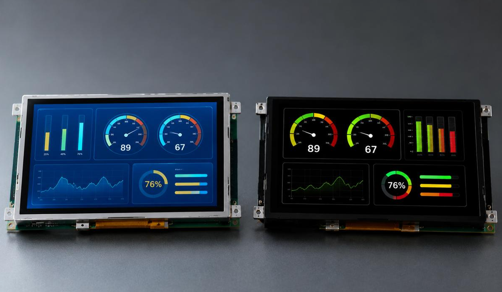
Two technologies dominate many modern display design discussions: Thin-Film Transistor Liquid Crystal Displays (TFT LCDs) and Organic Light-Emitting Diode (OLED) displays.
TFT LCD technology has long been used in industrial equipment because of its mature supply chain, flexible configurations, and suitability for applications requiring extended operating hours. OLED offers excellent contrast, deep blacks, and rapid pixel response, making it attractive for next-generation measurement instruments.
However, the selection process becomes more complicated when equipment must operate continuously, withstand temperature extremes, or display static measurement interfaces for thousands of hours.
Should engineers prioritize the proven reliability of industrial TFT LCDs or the optical advantages of OLED technology?
This guide examines the differences between TFT LCD and OLED displays from an industrial instrumentation perspective, helping product designers, OEM manufacturers, and procurement engineers make technically informed decisions.
1. Understanding TFT LCD and OLED Display Technology
How TFT LCD Technology Works
A TFT LCD uses a thin-film transistor array to control individual liquid crystal pixels. These pixels modulate light supplied by a separate backlight system to create images.
Unlike self-emissive displays, LCD pixels do not generate their own light.
The display’s performance depends on several components:
- Liquid crystal panel and TFT backplane
- LED backlight system
- Polarizers and optical films
- Driver IC and electronic interface
- Optional capacitive or resistive touch panel
- Protective cover glass and optical bonding materials
Industrial TFT LCD modules can be configured with different brightness levels, viewing angles, interfaces, and operating temperature specifications.
Key advantages of TFT LCD technology include:
- Broad availability of industrial display sizes and resolutions
- Flexible LED backlight brightness configurations
- Suitability for interfaces containing static information
- Mature manufacturing processes and competitive pricing
- Multiple integration options for embedded industrial systems
IPS TFT LCD technology also provides wide viewing angles and good color reproduction, making it suitable for modern graphical measurement interfaces.
How OLED Display Technology Works
OLED displays use organic semiconductor materials that emit light when electrical current passes through them.
Because each pixel generates its own light, OLED displays do not require a conventional LCD backlight.
Individual pixels can be turned off to produce extremely deep blacks, creating excellent contrast in dark environments.
Key advantages of OLED technology include:
- High contrast and excellent black-level performance
- Fast pixel response times
- Wide viewing angles
- Thin display structures
- Attractive dark-themed interfaces
- Potentially lower power consumption for dark, low-duty-cycle content
These characteristics make OLED particularly appealing for compact diagnostic devices, portable measurement equipment, and instruments requiring high visual contrast.
However, organic emissive materials age with use, creating additional considerations for industrial applications.
2. Optical Performance: Contrast, Color and Sunlight Readability
Display clarity is one of the most important factors in industrial instrumentation.
Unlike consumer electronics, measurement equipment must allow operators to recognize readings, warning indicators, and graphical information quickly and accurately under varying lighting conditions.
Contrast Ratio and Color Saturation
OLED generally delivers superior black levels because individual pixels can switch off completely.
In a dark environment, this produces an exceptionally high contrast ratio, often described as effectively infinite under ideal measurement conditions.
For example, a portable diagnostic instrument displaying bright waveforms against a black background can benefit from OLED’s ability to render dark areas without backlight leakage.
This is valuable for:
- Indoor electronic test instruments
- Medical diagnostic equipment
- Laboratory analyzers
- Portable inspection devices
- Waveform visualization systems
TFT LCDs use a backlight, which means black pixels may still transmit a small amount of light.
Nevertheless, modern IPS TFT LCDs can provide excellent color accuracy and sufficient contrast for many industrial applications.
Engineering recommendation: OLED is worth considering when deep blacks and visual separation between measurement elements are critical. TFT LCD is often sufficient when readability, consistency, and total system cost are the primary requirements.
Sunlight Readability: Why High-Brightness TFT LCDs Often Have an Advantage
Industrial instruments are frequently operated outdoors or in brightly illuminated production facilities.
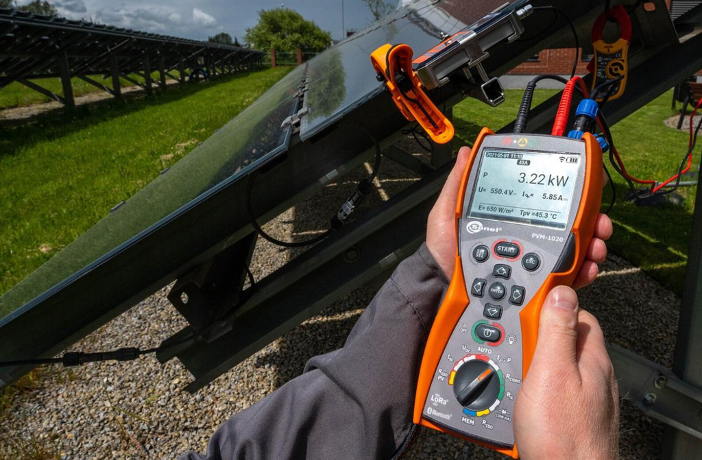
Examples include electrical inspection equipment, solar PV testing instruments, outdoor control terminals, and field maintenance devices.
In these environments, display readability depends not only on contrast ratio but also on luminance and reflected ambient light.
High-brightness TFT LCD modules can use specially designed LED backlights to improve visibility under strong ambient illumination.
Depending on the module and application, industrial TFT displays may be designed with luminance targets such as 800, 1,000, or 1,500 nits or higher.
However, the required brightness must be determined through application-specific testing rather than relying on a universal threshold.
Additional technologies can improve outdoor performance:
Ligação Ótica
Optical bonding fills the air gap between the display and front optical layers with a suitable transparent adhesive.
This can reduce internal reflections and improve perceived contrast.
Anti-Reflection (AR) Coating
AR coatings reduce surface reflections, improving visibility in brightly illuminated environments.
Anti-Glare (AG) Treatment
AG treatments scatter reflected light to reduce distracting glare, although they may also influence image sharpness.
Automatic Brightness Adjustment
Ambient light sensors and dimming control can help balance visibility, power consumption, and thermal performance.
OLED displays can also achieve high luminance, but outdoor performance depends on the selected panel, full-screen brightness, reflection management, thermal conditions, and aging requirements.
Engineering recommendation: For outdoor industrial instrumentation, a high-brightness TFT LCD with appropriate optical bonding and reflection control is often the more practical starting point.
3. Environmental Reliability: Temperature, Lifetime and Burn-In
Industrial display reliability must be evaluated under real operating conditions.
Temperature, continuous operation, humidity, mechanical stress, and interface content can affect display performance over time.
Wide Temperature Performance: -40°C to +85°C
Some industrial equipment must operate in environments ranging from extreme cold to elevated temperatures.
A commonly requested design range for demanding applications is -40°C to +85°C, although not every TFT LCD or OLED module supports this range.
Operating-temperature ratings must be verified for the exact display module and finished assembly.
TFT LCD Behavior at Low Temperatures
Liquid crystal response is temperature-dependent.
At low temperatures, increased liquid crystal viscosity can slow pixel transitions, potentially causing:
- Slower response times
- Motion blur or ghosting
- Reduced visual responsiveness
- Changes in optical characteristics
Engineers may address these limitations by choosing a qualified wide-temperature LCD module, incorporating thermal management, or adapting the display refresh and driving characteristics.
At high temperatures, LCD performance can also be affected by liquid crystal properties, polarizers, adhesives, and backlight components.
OLED Behavior at Temperature Extremes
OLED pixels do not rely on the mechanical reorientation of liquid crystals.
Consequently, OLED generally maintains faster pixel-response behavior at low temperatures than conventional LCD technology.
However, this does not mean OLED is immune to temperature-related problems.
Elevated temperatures can accelerate degradation of organic emissive materials, while low temperatures can influence electrical characteristics, drive requirements, and overall module reliability.
The display’s driver electronics, encapsulation, and other components must also meet the required environmental specifications.
Engineering recommendation: OLED offers an inherent pixel-response advantage in cold environments, but neither technology should be selected for extreme temperatures without confirming the module’s specified operating range and completing environmental testing.
Display Lifetime: Why Operating Hours Matter
Display lifetime is especially important in industrial instrumentation because equipment may remain in service for many years.
Some instruments operate only during measurement sessions, while others run continuously.
Consider the difference:
| Aplicação | Typical Display Usage Pattern | Reliability Priority |
|---|---|---|
| Portable digital multimeter | Intermittent operation | Power efficiency and readability |
| Industrial automation HMI | Long daily operating periods | Long-term stability |
| 24/7 monitoring instrument | Continuous operation | Display aging and component lifetime |
| Portable medical analyzer | Periodic measurement sessions | Clarity and power management |
| Outdoor electrical inspection device | Intermittent outdoor use | Sunlight readability and temperature tolerance |
TFT LCD lifetime is often influenced by LED backlight aging, which gradually reduces luminance.
OLED lifetime is influenced by the cumulative operation of its emissive pixels, with aging dependent on brightness, content, operating temperature, and drive conditions.
For both technologies, manufacturers may specify lifetime under defined conditions, such as the time required for brightness to decrease to a particular percentage of its initial value.
These measurements cannot be compared directly unless the definitions and test conditions are equivalent.
OLED Burn-In: A Critical Concern for Industrial Instruments
One of the most important limitations of OLED in instrumentation is the potential for permanent image retention, commonly known as burn-in.
Burn-in results from uneven aging of OLED pixels.
For instance, an instrument may display the same elements repeatedly:
- Measurement scales
- Battery indicators
- Fixed numerical labels
- Menu icons
- Warning symbols
- Navigation bars
When particular pixels remain illuminated at higher intensities than surrounding pixels for extended periods, their luminance can decline at different rates.
This can eventually create visible residual patterns.
Industrial instrumentation is particularly susceptible because user interfaces often include fixed visual elements.
How Can Engineers Reduce OLED Burn-In?
Several design techniques can reduce burn-in risk:
- Dynamic UI Layouts: Periodically reposition suitable interface elements to distribute pixel usage.
- Automatic Brightness Control: Avoid unnecessarily high luminance.
- Screen Timeout: Switch the display off when the instrument is not being used.
- Dark Interface Design: Minimize the number of continuously illuminated pixels.
- Pixel Shifting: Apply subtle image movement where acceptable for measurement accuracy and usability.
- Application-Specific Validation: Test the display using realistic interface patterns and operating schedules.
These measures can reduce differential pixel aging but cannot eliminate it completely.
TFT LCDs may also exhibit temporary image retention, but they do not experience the same organic emissive pixel-aging mechanism as OLED.
Engineering recommendation: For instruments displaying fixed numerical scales or status interfaces continuously, TFT LCD is generally the lower-risk choice.
4. Power Consumption: Is OLED Always More Energy Efficient?
OLED is frequently described as an energy-saving display technology.
However, actual power consumption depends heavily on the displayed content.
TFT LCD Power Characteristics
In most conventional TFT LCDs, the LED backlight accounts for a substantial portion of display power consumption.
At a fixed backlight setting, power consumption generally changes relatively little between bright and dark image content.
This provides predictable behavior for interfaces containing multiple colors, diagrams, and bright backgrounds.
Backlight dimming can further reduce power consumption.
OLED Power Characteristics
OLED power consumption varies according to the number of illuminated pixels, their brightness, and their color.
A mostly black interface with limited illuminated text or graphics may consume less power than a comparable backlit TFT LCD.
However, displaying predominantly white backgrounds or high-brightness graphics can increase OLED power consumption substantially.
For example, a handheld electrical tester with a black screen and occasional bright readings may be a favorable OLED application.
A continuously operating industrial analyzer displaying a bright white interface may produce a less favorable power profile.
Power Consumption Comparison
| Operating Condition | LCD TFT | OLED |
|---|---|---|
| Dark graphical interface | Backlight still consumes power | Potential efficiency advantage |
| Bright white interface | Relatively predictable backlight demand | Higher emissive power demand |
| Intermittent operation | Efficient with backlight shutdown | Attractive for dark, short-duration use |
| Continuous high-brightness operation | Often practical with thermal design | Requires careful power and aging evaluation |
| Automatic dimming | Supported through backlight control | Supported through emissive brightness control |
Engineering recommendation: Compare complete module power consumption using representative screen content, required brightness, and actual duty cycles rather than assuming OLED always consumes less energy.
5. TFT LCD vs. OLED: Technical Comparison for Industrial Instrumentation
The following table summarizes the most relevant selection factors for industrial hardware developers.
| Evaluation Criteria | LCD TFT industrial | Exibição OLED |
|---|---|---|
| Display principle | Backlit liquid crystal | Self-emissive organic pixels |
| Black-level performance | Limited by backlight leakage | Excelente |
| Contrast ratio | Good to excellent, depending on panel | Extremely high in dark conditions |
| Color performance | Good, especially IPS TFT | Excellent on suitable modules |
| Sunlight readability | Strong options with high-brightness backlights | Depends on luminance and optical design |
| Pixel response time | Temperature- and panel-dependent | Generally faster |
| Low-temperature behavior | Possible liquid crystal response slowdown | Fast pixel response, but module rating still matters |
| High-temperature reliability | Depends on LCD stack and backlight design | Organic emitter aging requires attention |
| Static image suitability | Generally favorable | Burn-in risk must be managed |
| Continuous 24/7 operation | Often a practical choice | Requires careful lifetime validation |
| Consumo de energia | Mainly influenced by backlight settings | Strongly dependent on image content |
| Module thickness | Includes backlight assembly | Can be thinner |
| Cost | Often competitive in standard industrial sizes | Varies significantly by module |
| Size and interface availability | Broad industrial ecosystem | More application-dependent |
| Personalização | Broad module and touch integration options | Depends on OLED module and supplier |
| Typical industrial applications | HMIs, outdoor testers, fixed instruments | Portable analyzers, compact diagnostic devices |
Nota: These are general technology characteristics, not guaranteed specifications. Actual performance must be confirmed through individual module datasheets and qualification testing.
6. Application-Based Selection: Which Technology Fits Your Instrument?
The most effective display selection begins with the equipment’s operating environment rather than its visual appearance.
Application 1: Outdoor Electrical Measurement Instruments
Recommended starting point: High-Brightness TFT LCD
Outdoor measurement devices must remain readable in sunlight while tolerating temperature variations.
Examples include:
- Solar PV testing instruments
- Portable electrical inspection equipment
- Power quality analyzers
- Outdoor diagnostic terminals
A high-brightness IPS TFT LCD with appropriate cover glass, AR treatment, and optical bonding can provide a practical balance of readability and durability.
Application 2: Industrial Control Panels and Factory HMIs
Recommended starting point: Industrial TFT LCD
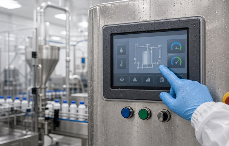
Industrial control interfaces typically display static menus, status indicators, process diagrams, and measurement data for long periods.
TFT LCD technology is often preferable because it avoids OLED’s differential emissive aging mechanism and offers multiple configurations for long-running industrial products.
Application 3: Portable Digital Multimeters and Compact Test Instruments
Recommended starting point: OLED or IPS TFT LCD
Handheld instruments benefit from compact dimensions, clear measurement readings, and low power consumption.
OLED is attractive when the interface uses predominantly dark graphics and the display operates intermittently.
IPS TFT LCD may be preferable when the device needs a brighter interface, a larger screen, or a lower-cost standard module.
Application 4: Medical Diagnostic and Laboratory Instruments
Recommended starting point: Application-dependent
Medical and laboratory equipment often requires precise visual presentation and reliable operation.
OLED can be suitable for compact instruments displaying changing waveforms, graphical results, or diagnostic images in controlled indoor lighting.
TFT LCD is often advantageous for equipment requiring continuous operation, fixed interfaces, or a broad choice of module sizes.
In both cases, engineers must also evaluate cleaning compatibility, optical performance, electrical safety requirements, and applicable product-level regulations.
Application 5: Continuous Monitoring and Data Acquisition Systems
Recommended starting point: Industrial TFT LCD
Monitoring instruments often show the same interface throughout extended operating periods.
A TFT LCD can provide a more manageable aging profile for fixed information displays.
OLED may still be considered if the interface can be redesigned to distribute pixel usage and the operating lifetime has been adequately validated.
7. Industrial Display Decision Matrix
Use this matrix during the early stages of equipment development.
| Design Requirement | Preferred Starting Point | Key Engineering Consideration |
|---|---|---|
| Outdoor sunlight exposure | Ecrã LCD TFT de alto brilho | Luminance, reflection and thermal management |
| Continuous static interface | LCD TFT | Long-term image stability |
| High contrast in dark environments | OLED | Black level and dark UI design |
| Fast response in cold conditions | OLED candidate | Verify complete module temperature qualification |
| Extended 24/7 operation | LCD TFT | Backlight lifetime and thermal design |
| Compact handheld instrument | OLED or IPS TFT | Battery life, thickness and cost |
| Fixed measurement scales | LCD TFT | Reduced permanent burn-in risk |
| Dynamic waveform display | OLED or suitable TFT | Response time, refresh rate and latency |
| Long OEM production lifecycle | Often TFT LCD | Supply continuity and replacement strategy |
| Low-cost color GUI | Standard TFT LCD | Total module and integration cost |
The matrix is intended for preliminary engineering decisions. Final selection should always follow sample evaluation and reliability qualification.
8. How to Select the Right OEM Display Module
For industrial instrument manufacturers, selecting a display involves much more than comparing screen technology.
The complete display assembly must integrate with the product’s electronics, mechanical enclosure, and operating environment.
Step 1: Define the Operating Environment
Document the expected temperature range, lighting conditions, humidity, vibration exposure, and operating schedule.
For applications requiring extreme temperatures, obtain the precise module-level operating and storage temperature specifications.
Step 2: Evaluate the User Interface
Determine whether the interface contains primarily static elements or frequently changing graphics.
For OLED, evaluate average pixel brightness, static content duration, and expected cumulative operating hours.
Step 3: Confirm Optical Requirements
Specify:
- Tamanho e resolução do ecrã
- Required brightness
- Ângulo de visão
- Contrast requirements
- Funcionalidade tátil
- Cover-glass characteristics
- Optical bonding requirements
Outdoor instruments should be evaluated under representative ambient lighting conditions.
Step 4: Review Electrical Integration
Confirm compatibility with the host processor and system architecture.
Depending on the selected module, interfaces may include SPI, MCU, RGB, MIPI DSI, or other industrial display interfaces.
Engineers should also evaluate supply voltage, display power, startup sequencing, EMI behavior, and software-driver requirements.
Step 5: Calculate Total Cost of Ownership
Unit price is only one component of display selection.
Consider:
- Display module cost
- Touch-panel integration
- Optical bonding and protective glass
- Backlight or emissive lifetime
- Thermal management requirements
- Tooling and customization costs
- Long-term component availability
- Qualification and potential redesign costs
An apparently inexpensive display may create higher lifecycle costs if it requires extensive redesign or frequent replacement.
Step 6: Conduct Application-Specific Reliability Tests
Before mass production, validate representative modules under the intended operating conditions.
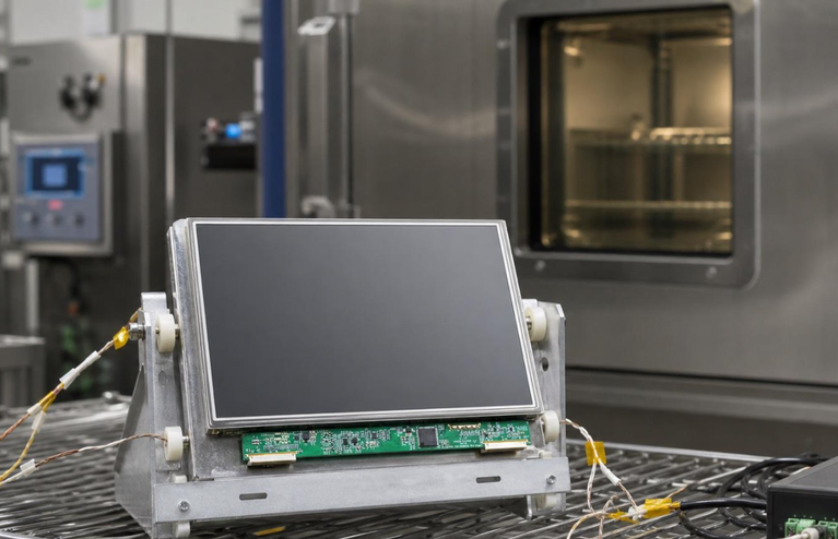
Recommended evaluations include temperature cycling, continuous-operation aging, sunlight readability, vibration where applicable, and electrostatic discharge testing.
For OLED modules, add representative static-interface aging tests.
For TFT LCD modules, evaluate low-temperature response and backlight luminance degradation.
9. Qihantech: OEM/ODM Display Solutions for Industrial Instrument Manufacturers
Selecting a suitable display technology requires coordination between optical performance, electronic interfaces, mechanical integration, and long-term equipment requirements.
Qihantech provides TFT LCD modules, OLED display solutions, and touch-panel integration services for OEM/ODM applications.
For industrial instrumentation developers, the objective is not simply to select a display with attractive specifications. It is to identify a practical module that matches the equipment’s installation environment, interface architecture, user experience, and manufacturing requirements.
Depending on project requirements and module availability, Qihantech can help customers evaluate solutions involving:
- Industrial TFT LCD Displays: Display configurations for measurement devices, embedded controllers, and industrial equipment.
- OLED Display Modules: High-contrast display options for compact instruments and graphical interfaces.
- Capacitive and Resistive Touch Panels: Touch interfaces selected according to operating conditions and input requirements.
- Custom Display Integration: Evaluation of screen dimensions, cover glass, mechanical design, and electronic interfaces.
- Optical Integration: Display and touch-stack considerations for equipment requiring improved visibility and protection.
For OEM and ODM manufacturers, early collaboration on display specifications can help reduce integration risks and avoid unnecessary redesign during product development.
Explore Qihantech’s industrial display solutions at https://qihantech.com/.
10. Frequently Asked Questions (FAQ)
Q1. Is TFT LCD or OLED better for industrial instruments?
TFT LCD is generally a practical option for industrial instruments requiring continuous operation, static interfaces, or outdoor readability.
OLED is attractive for portable instruments with dark interfaces, dynamic content, and demanding contrast requirements.
The final decision depends on operating conditions, lifetime, power requirements, and module specifications.
Q2. Does OLED always consume less power than TFT LCD?
No. OLED power consumption depends on pixel brightness and displayed content.
Dark interfaces may provide power savings, while bright white interfaces can consume substantial energy.
TFT LCD power consumption is more strongly influenced by its backlight settings.
Q3. Can OLED displays operate at -40°C?
Some specialized OLED modules may support low-temperature operation, but -40°C capability cannot be assumed.
Engineers must verify the exact module’s operating-temperature rating and electrical performance under the required conditions.
Q4. What causes OLED burn-in in industrial measurement equipment?
OLED burn-in results from uneven degradation of emissive pixels.
Static measurement scales, logos, warning indicators, and navigation elements displayed for extended periods can accelerate differential aging.
Brightness management, screen timeouts, and dynamic interface design can reduce the risk.
Q5. Why are TFT LCDs commonly used in outdoor electrical testers?
Industrial TFT LCDs offer high-brightness backlight options and can be combined with optical bonding and anti-reflection treatments.
These features can improve visibility under sunlight when properly integrated into the finished instrument.
Q6. Is an IPS TFT LCD better than a standard TFT LCD?
IPS is a type of TFT LCD technology.
Compared with some conventional TN LCD configurations, IPS generally provides wider viewing angles and more consistent color reproduction.
However, brightness, response time, temperature capability, and cost should still be evaluated for the specific module.
Q7. Can TFT LCD and OLED displays support capacitive touchscreens?
Yes. Both technologies can be integrated with compatible capacitive touch panels.
The complete assembly must be designed around the cover-glass thickness, touch controller, electrical noise environment, and mechanical requirements.
Q8. Which display technology is better for long-term OEM manufacturing?
TFT LCD frequently provides broader standard module availability and interface choices in industrial applications.
However, long-term supply continuity depends on the exact module, manufacturer, component lifecycle, and procurement agreement.
Q9. How should engineers compare OLED and TFT LCD lifetime?
Lifetime specifications should be compared using equivalent measurement definitions and operating conditions.
Engineers should review luminance degradation thresholds, display brightness, temperature, usage pattern, and expected operating hours.
A single advertised lifetime value is not enough to predict field reliability.
Q10. What information should be provided when requesting a custom industrial display?
OEM customers should ideally provide:
- Required display size and resolution
- Application and equipment type
- Operating and storage temperatures
- Brightness and viewing-angle requirements
- Required electrical interface
- Touchscreen and cover-glass specifications
- Mechanical drawings or installation constraints
- Expected annual order volume and product lifecycle
These details allow the display supplier to recommend an appropriate solution and identify potential integration risks.
Conclusion: TFT LCD or OLED — Which Should You Choose?
The decision between TFT LCD and OLED technology should be driven by the instrument’s actual operating requirements rather than display appearance alone.
Choose TFT LCD when your instrument requires:
- Continuous operation and predominantly static interfaces
- High-brightness outdoor visibility
- Broad industrial size and interface choices
- Competitive total system cost
- Predictable integration for long-term equipment programs
Consider OLED when your instrument prioritizes:
- Excellent contrast and deep black levels
- Compact construction
- Fast pixel response
- Dark-themed graphical interfaces
- Intermittent operation with controlled display brightness
Neither technology is universally superior.
For industrial equipment designers, the best display is the one that satisfies optical, electrical, environmental, reliability, and procurement requirements over the intended service life.
Looking for an industrial TFT LCD or OLED display for your next instrumentation project?
Contacto Qihantech to discuss display technology selection, OEM/ODM customization, and integration requirements for your industrial measurement equipment.
Website: https://qihantech.com/

 English
 Português
 Français
 Deutsch
 Español
 Русский