Auswahl eines TFT-LCD mit kapazitiver Berührung ist nicht einfach eine Frage der Abstimmung von Bildschirmgröße und Auflösung. Das Display, der Berührungssensor, der Controller, das Deckglas, der Klebstoff, die Firmware, das Gehäuse und die Host-Elektronik verhalten sich als ein System. Eine Änderung an einer beliebigen Schicht kann die optische Qualität oder die Berührungsleistung beeinträchtigen.
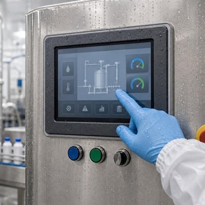
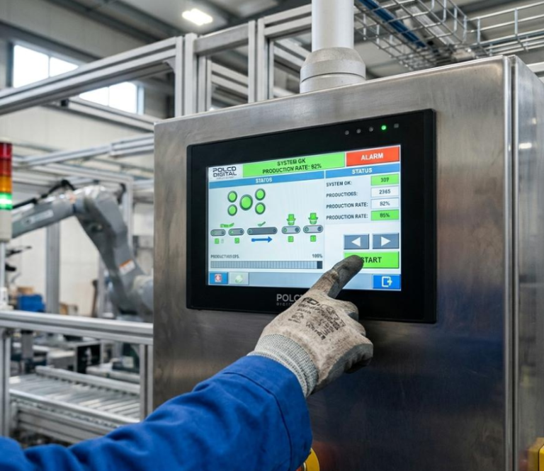
Dies ist in industriellen Geräten von Bedeutung. Der Bediener trägt möglicherweise Handschuhe. Die Oberfläche kann nass sein oder wiederholt gereinigt werden. Ein Motor, ein Ladegerät oder ein Schaltnetzteil kann elektrisches Rauschen verursachen. Das Produkt kann außerdem eine dicke dekorative Abdeckscheibe, eine abgedichtete Frontplatte oder einen zuverlässigen Betrieb über einen weiten Temperaturbereich erfordern.
Ein erfolgreiches industrielles Touchscreen-Display beginnt beim Bediener und der Umgebung und arbeitet sich dann nach innen zur Elektronik vor. Dieser Leitfaden bietet eine praktische Auswahlmethode für kleine industrielle TFT-LCD-Projekte.
Die kurze Antwort
Wählen Sie ein PCAP-TFT-Display wenn die Anwendung von einer langlebigen Glasfront, guter optischer Klarheit und Multi-Touch-Gesten profitiert. Wählen Sie resistive Berührung, wenn zuverlässige Aktivierung mit nahezu jedem Handschuh oder passiven Stift wichtiger ist als Multi-Touch und eine smartphone-ähnliche Benutzererfahrung.
Für ein industrielles kapazitives Touch-Display definieren Sie diese Anforderungen, bevor Sie ein Angebot anfordern:
- Displaygröße, Auflösung, Helligkeit und Schnittstelle
- Anforderungen an bloßen Finger, Handschuh und Stift
- Erwartete Wasser-, Reinigungs- und Kontaminationsbedingungen
- Dicke, Form, Bedruckung und Oberflächenbehandlung des Deckglases
- Erforderliche Berührungspunkte und Gesten
- Host-Schnittstelle, normalerweise I²C oder USB für PCAP
- Betriebstemperatur und elektrische Rauschumgebung
- Bonding-Verfahren und Gehäusekonstruktion
Behandeln Sie “industrielle Qualität”, “Handschuhberührung” oder “wasserdichte Berührung” nicht als vollständige Spezifikationen. Jeder Begriff erfordert eine messbare Testbedingung.
Was ist eine kapazitive Berührung TFT-LCD-Display?
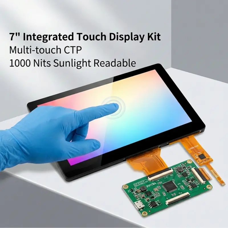
Ein TFT-LCD mit kapazitiver Berührung kombiniert ein Dünnschichttransistor-Flüssigkristalldisplay mit einem projiziert-kapazitiven Touchpanel, häufig als PCAP oder CTP abgekürzt.
Das TFT-LCD erzeugt das Bild. Der kapazitive Berührungssensor erkennt Änderungen in einem elektrischen Feld, wenn sich ein Finger oder ein anderes geeignetes leitfähiges Objekt der Oberfläche nähert. Ein Touch-Controller verarbeitet diese Änderungen und meldet Positionsdaten an den Host-Prozessor.
Die resultierende Baugruppe kann Folgendes umfassen:
- Ein TFT-LCD-Modul und eine Hintergrundbeleuchtung
- Einen projiziert-kapazitiven Berührungssensor
- Einen Touch-Controller-IC und Firmware
- Optischen Klebstoff oder Umfangsband
- Eine kundenspezifische Abdeckscheibe
- Separate Display- und Touch-FPCs oder Steckverbinder
- Eine optionale Treiber- oder Schnittstellenplatine
Diese Schichten sollten gemeinsam spezifiziert werden. Beispielsweise schwächt eine Erhöhung der Deckglasdicke das Berührungssignal. Das Hinzufügen eines bedruckten Rahmens verändert die Umgebung des Sensors. Eine Änderung des Display-Takts oder der Stromversorgung kann das elektrische Rauschen verändern. Das Ersetzen von Luftbonding durch optisches Bonding verändert den optischen und mechanischen Stapel.
Häufige PCAP-Sensorstrukturen
Industrielle PCAP-Panels sind in mehreren Konstruktionen erhältlich. Häufige Beispiele sind Glas-Glas, Glas-Film und Glas-Film-Film, oft als G+G, G+F und G+FF bezeichnet.
G+G verwendet Glas für die Abdeckscheibe und das Sensorsubstrat. Es wird häufig wegen dimensionaler Stabilität, Oberflächenhaltbarkeit und einer robusten Frontschnittstelle gewählt.
G+F und G+FF verwenden eine oder mehrere Filmsensorsschichten hinter der Abdeckscheibe. Diese Strukturen können dünne oder leichte Designs unterstützen und bieten möglicherweise mehr Flexibilität für bestimmte Formen und Konstruktionen.
Keine Struktur ist automatisch für jedes Produkt die beste. Die Entscheidung sollte Dicke, optische Leistung, Rahmen-Design, Stoßanforderungen, Sensorgröße, Werkzeuge und erwartetes Volumen berücksichtigen.
Beginnen Sie mit dem Bediener, nicht mit der Berührungstechnologie
Bevor Sie PCAP und resistive Berührung vergleichen, dokumentieren Sie, wie der Bediener das Gerät verwenden wird.
Stellen Sie praktische Fragen:
- Wird der Bediener einen bloßen Finger, einen medizinischen Handschuh, einen Arbeitshandschuh oder einen isolierten Winterhandschuh verwenden?
- Ist ein passiver Stift erforderlich?
- Erfordert die Schnittstelle Multi-Touch-, Pinch- oder Rotationsgesten?
- Wie groß sind die Tasten und Berührungsziele?
- Ist das Gerät fest installiert, handgehalten oder fahrzeugmontiert?
- Wird der Bediener den Bildschirm berühren, während das Gerät vibriert?
- Soll das System Eingaben im nassen Zustand akzeptieren oder nur falsche Berührungen ablehnen?
- Was muss geschehen, wenn Wasser auf der Oberfläche verbleibt?
Diese Fragen bestimmen oft die richtige Technologie zuverlässiger als eine allgemeine Vorliebe für kapazitive Berührung.
PCAP-Touchscreen vs. resistiver Touchscreen
Beide Technologien können in industriellen Geräten funktionieren, aber sie reagieren unterschiedlich auf Eingaben.
Wie PCAP-Berührung funktioniert
Projiziert-kapazitiver Touch misst Kapazitätsänderungen über einen strukturierten Sensor. Er unterstützt eine versiegelte Glasfront, hohe optische Klarheit und Multitouch-Bedienung. Mit dem richtigen Controller, Sensor und Tuning kann er auch spezifizierte Handschuhe und nasse Bedingungen unterstützen.
PCAP wird häufig in industriellen HMIs, medizinischen Geräten, Fahrzeugsteuerungen, Smart-Home-Panels und Handmessgeräten eingesetzt, wo Aussehen, Gesten und lange Lebensdauer der Frontoberfläche wichtig sind.
So funktioniert resistiver Touch
Ein resistiver Touchscreen erkennt physischen Druck, der leitfähige Schichten in Kontakt bringt. Er kann normalerweise mit einem Finger, den meisten Handschuhen oder einem passiven Stift bedient werden.
Resistiver Touch bleibt nützlich für Geräte mit einfachen Schnittstellen, Einzelpunkt-Eingabe oder anspruchsvollen Handschuh- und Stift-Workflows. Er bietet normalerweise nicht die gleiche Multitouch-Erfahrung oder Glasfront-Optik wie PCAP.
Vergleich von PCAP und resistivem Touch
| Auswahlfaktor | PCAP-Touchscreen | Resistiver Touchscreen |
|---|---|---|
| Eingabemethode | Finger und unterstützte Handschuhe; aktive Stiftoptionen hängen vom Controller ab | Finger, die meisten Handschuhe und passiver Stift |
| Multi-Touch | Unterstützt durch geeignete Controller | Normalerweise Einzelberührung |
| Frontoberfläche | Langlebiges Deckglas kann die Benutzeroberfläche bilden | Flexible obere Schicht ist typisch |
| Optisches Erscheinungsbild | Hohe Klarheit ist erreichbar | Zusätzliche Schichten können die Klarheit verringern |
| Gestenunterstützung | Geeignet für Wisch-, Zoom- und Multifinger-Gesten | Am besten für einfache Druck-und-Zieh-Steuerung |
| Nasser Betrieb | Erfordert definierte Wasserbehandlung und Abstimmung | Druckeingabe kann weniger empfindlich auf kapazitive Effekte reagieren, aber eine Versiegelung ist weiterhin erforderlich |
| Controller-Schnittstelle | Häufig I²C oder USB | Häufig 4-Draht- oder 5-Draht-Analogeingang |
| Anpassung | Sensor, Decklinse, Druck, Controller und Firmware | Umriss-, Tail-, Steckverbinder- und Overlay-Optionen |
| Beste Eignung | Moderne industrielle HMI- und versiegelte Glasfront-Produkte | Stiftbasierte oder universelle Handschuhanwendungen |
Die richtige Wahl folgt dem Workflow. PCAP ist nicht automatisch industrieller, und resistiver Touch ist nicht automatisch veraltet.
Touch-Empfindlichkeit mit Handschuhen
Ein bloßer Finger erzeugt ein stärkeres kapazitives Signal als ein Finger, der durch einen Handschuh und Deckglas vom Sensor getrennt ist. Um Handschuhe zu unterstützen, müssen Sensor und Controller eine kleinere Änderung erkennen, ohne übermäßig empfindlich auf Rauschen oder Feuchtigkeit zu reagieren.
“Handschuhbetrieb” sollte unter Angabe des tatsächlichen Handschuhtyps spezifiziert werden. Ein dünner Nitril-Untersuchungshandschuh, ein beschichteter Montagehandschuh, ein Lederarbeitshandschuh und ein isolierter Winterhandschuh stellen sehr unterschiedliche elektrische und mechanische Bedingungen dar.
Nehmen Sie diese Details in die Touch-Spezifikation auf:
- Handschuhhersteller und Teilenummer, falls verfügbar
- Handschuhmaterial und -dicke
- Ob der Handschuh trocken, feucht, kontaminiert oder über einem anderen Handschuh getragen wird
- Minimale erforderliche Touch-Zielgröße
- Erforderliche Aktionen wie Tippen, Ziehen, langes Drücken und Gesten
- Maximale Deckglasdicke
- Akzeptable Reaktionszeit und Rate verpasster Berührungen
Stellen Sie während der Entwicklung serienreife Handschuhmuster bereit. Ein Touchpanel, das für einen Handschuh abgestimmt wurde, kann nicht als Unterstützung für jeden Handschuh vorausgesetzt werden.
Verringert dickes Deckglas die Touch-Empfindlichkeit?
Ja. Eine Vergrößerung des Abstands zwischen Bediener und Sensor verringert die kapazitive Kopplung. Glaszusammensetzung, Klebstoffdicke, gedruckte Tinte, Luftspalte und nahe Metallteile können das Signal ebenfalls beeinflussen.
It may be possible to operate through several millimeters of cover glass, but a thickness value alone cannot confirm performance. The final sensor pattern, controller, firmware, grounding and enclosure must be evaluated together.
Touch Operation with Wet Hands and Water
Water is conductive enough to disturb a capacitive field. Droplets can resemble touches, connect multiple sensor channels or interfere with a valid finger input.
An industrial PCAP controller may use water-rejection algorithms to distinguish between a finger and moisture. Depending on the design, the touchscreen may continue to accept a single-finger touch, limit gestures or temporarily reject all input when the surface is heavily wet.
The safest response depends on the product. A consumer appliance may prioritize continued operation. A machine control may prioritize preventing an unintended command.
Define the exact water condition:
- Scattered rain droplets
- A wet finger on a dry screen
- Cleaning spray
- Flowing water
- Condensation near the edge
- Salt water or conductive process fluid
- A fully flooded surface
Also define the expected system response. “No ghost touches during rain” is different from “full touch operation under running water.”
Water handling does not make a display waterproof. Ingress protection depends on the cover lens, adhesive, gasket, housing, cable exits and complete enclosure design.
Cover Glass, Surface Treatment and Durability
The cover lens is the part users see and touch, but it also affects optics, sensing and mechanical integration.
Cover-Glass Decisions to Specify
A custom cover lens may define:
- Outer dimensions and thickness
- Rectangular, rounded or irregular shape
- Edge finish and corner radius
- Viewing window and black-mask dimensions
- Logo and icon printing
- Transparent touch keys or indicator windows
- Holes, slots and mounting features
- Adhesive border and sealing area
- AR, AG or AF surface treatment
The black mask must hide the adhesive, sensor traces and display structure without clipping the active area. Tight alignment tolerances should be agreed across the TFT LCD, touch sensor, printing and housing.
AR, AG and AF Are Different Treatments
AR, or anti-reflection treatment, reduces mirror-like reflections. It is useful when strong lighting or outdoor use makes the cover behave like a mirror.
AG, or anti-glare treatment, diffuses reflected light. It can reduce distracting glare, but excessive haze may soften text and create sparkle over small pixels.
AF, or anti-fingerprint treatment, reduces the visibility of fingerprints and can improve cleanability and touch feel. Its abrasion life and compatibility with cleaning chemicals should be checked for the intended environment.
These treatments should be selected from real optical and maintenance requirements. Adding every available coating does not guarantee a better display.
What Does “Rugged Touch Screen” Mean?
“Rugged” is not a complete engineering specification. Translate it into product-level requirements such as:
- Impact energy and test method
- Surface hardness and abrasion test
- Chemical resistance and cleaning cycle
- Operating and storage temperature
- Vibration and mechanical shock
- UV-Bestrahlung
- Ingress-protection target
- Expected field life
A strong cover lens alone does not certify a finished product to an IK or IP rating. Those ratings apply to the tested enclosure and assembly.
Air Bonding vs. Optical Bonding
Perimeter bonding attaches the touch panel around its edges and leaves an air gap above the TFT LCD. It is economical and can simplify rework, but the internal optical boundaries produce reflections.
Optical bonding fills the gap with a transparent adhesive. This can reduce internal reflection, improve perceived contrast and provide a more integrated appearance. It can also remove the cavity in which condensation might otherwise form.
Optical bonding is particularly useful when the industrial touchscreen display is used outdoors, viewed under strong lighting or expected to deliver premium optical quality.
The decision should also consider cost, repair strategy, bonding yield, cover size, temperature range and the risk of visible mura or bubbles. Once optically bonded, replacing one layer independently is generally impractical.
Choosing Touch Interfaces for Industrial HMIs
A TFT LCD with capacitive touch normally has two separate electronic interfaces. The display interface carries image data. The touch interface carries coordinate and gesture data. They should not be confused.
Common TFT LCD Interfaces
Small-size TFT LCD modules may use SPI, MCU, RGB or MIPI DSI, depending on resolution, refresh rate and processor platform. Larger or integrated HMI displays may also use LVDS, eDP, HDMI or another converted interface.
Choose the display interface by checking:
- Native interface supported by the host processor
- Required resolution, color depth and frame rate
- Available GPIO count and PCB routing space
- Cable length and EMI constraints
- Driver availability and software effort
- Power-up sequence and backlight control
I²C for Capacitive Touch
I²C is common for embedded PCAP controllers. It uses few signal lines and connects directly to many microcontrollers and application processors.
Confirm the controller address, interrupt line, reset line, voltage level, maximum bus length, Linux or RTOS driver support and firmware-update method. Long cables or electrically noisy equipment may require careful routing and validation.
USB for Capacitive Touch
USB touch is useful when the host is a PC-class platform, embedded Linux computer or industrial controller that supports USB Human Interface Device operation.
It can reduce driver-development effort when standard HID behavior is available. The trade-offs may include connector size, cable routing, power architecture and boot-time behavior.
Do Not Choose the Interface in Isolation
The correct interface is the one supported across the full product lifecycle. Check development tools, operating-system support, controller availability, firmware ownership and the process for future tuning updates.
Record the approved touch-controller firmware with the display assembly part number. A replacement controller or revised tuning file can change glove, water and edge-touch performance even when the mechanical drawing remains unchanged.
Electrical Noise and Grounding
Motors, inverters, switching regulators, chargers and radios can interfere with projected capacitive sensing. Raising touch sensitivity for gloves or thick glass may reduce noise margin.
Plan the hardware before relying on software filtering:
- Use a clean and stable touch-controller power supply
- Keep sensor and FPC routing away from switching nodes
- Define grounding between the display, touch controller, chassis and host
- Review shield design and termination
- Check metal features close to the sensor edge
- Test with the backlight at maximum brightness
- Test while motors, radios and chargers operate
A quiet evaluation board on a laboratory bench does not reproduce the final HMI. Final tuning should take place in the production-intent enclosure with the real power system and operating equipment active.
A Step-by-Step Selection Process
Step 1: Freeze the Viewing Requirement
Define active area, resolution, orientation, brightness, viewing angle and viewing distance. Confirm whether the display will be read indoors, outdoors or through polarized sunglasses.
Step 2: Describe the Operator
Identify finger, glove and stylus use. Define the required gestures and minimum touch-target size. Provide representative gloves rather than a general description.
Step 3: Describe the Environment
List temperature, moisture, cleaning agents, vibration, nearby electrical equipment and the required enclosure rating.
Step 4: Design the Cover Lens
Specify dimensions, thickness, shape, printing, edge finish, treatments and bonding area. Coordinate the viewing window and touch active area with the housing.
Step 5: Select the Display and Touch Interfaces
Match the TFT bandwidth and touch communication method to the host hardware and software. Confirm driver support, voltage levels, connectors and cable length.
Step 6: Choose the Bonding Method
Use the actual optical, environmental, cost and service requirements to compare air bonding and optical bonding.
Step 7: Build and Tune the Complete Assembly
Tune PCAP sensitivity after the display, cover lens, bonding, grounding, enclosure and power system are representative of production.
Step 8: Validate the Operator Workflow
Test complete tasks, not only isolated touch points. An operator should be able to select controls, drag values, dismiss alarms and navigate the HMI under the expected glove, water, temperature and vibration conditions.
Industrial Touchscreen Validation Matrix
| Test condition | What to verify |
|---|---|
| Bare dry finger | Accuracy, latency, edge response and gestures |
| Each specified glove | Tap, drag, long press and missed touches |
| Wet finger | Defined touch behavior and recovery |
| Water droplets | No unsafe false activation |
| Maximum cover thickness | Sensitivity margin and edge performance |
| Minimum and maximum temperature | Startup, tracking and recalibration |
| Motor or inverter operating | No ghost touches or controller lockup |
| Charger and communications active | Stable input in every power mode |
| Production cleaning chemical | Coating durability and reliable operation |
| Vibration or vehicle motion | Usable targets and no accidental input |
Acceptance criteria should be written before testing. “Touch works” is not measurable. Define allowable position error, missed-touch rate, false-touch behavior, response time and recovery after water or noise exposure.
Recommended Applications
Industrial Automation and Machine Controls
A PCAP TFT display can provide a sealed, easy-to-clean operator surface for compact machine controls, diagnostic panels and production equipment. Large touch targets and controlled false-touch behavior are important around moving machinery.
Medical and Laboratory Equipment
Medical and laboratory interfaces often prioritize cleanability, glove use, optical clarity and consistent touch response. The cover treatment and bonding materials should be checked against the intended disinfectants and cleaning cycles.
Vehicle and Transportation Displays
Vehicle-mounted displays may experience sunlight, vibration, electrical noise and large temperature changes. Glove use, polarized sunglasses, connector retention and display readability should be evaluated together.
Handheld Test and Measurement Instruments
Small TFT LCDs with capacitive touch can support compact graphical interfaces in portable meters and field instruments. Battery life, wet operation and one-handed use may influence the display size and UI design.
Smart Home and Building Controls
Wall-mounted controllers benefit from a clean glass front, custom printing and intuitive gestures. The designer should still check standby power, mounting-ground effects and long-term controller availability.
What to Include in an RFQ
Provide the following information when requesting a custom TFT LCD with capacitive touch:
- TFT LCD size, resolution and preferred viewing direction
- Required brightness and lighting environment
- Display interface and host processor
- Touch technology and number of touch points
- I²C or USB touch interface preference
- Required operating system or driver support
- Glove type and thickness
- Water condition and required behavior
- Cover-lens drawing, thickness and material
- Printing, logo and surface-treatment requirements
- Optical or perimeter bonding preference
- Operating and storage temperatures
- Mechanical shock, vibration, IP or IK targets
- Expected annual quantity and project lifetime
- Prototype schedule and validation requirements
Photos of the enclosure, a mechanical drawing and details of the host electronics allow a supplier to identify risks earlier.
How QIHAN Supports Custom TFT and Touch Projects
QIHAN manufactures and supplies small and medium-sized TFT LCD modules for industrial, medical, HMI, transportation and embedded applications.
QIHAN’s published touch capabilities include projected capacitive and resistive touch options. Standard PCAP offerings include G+G, G+F and G+FF structures, with I²C and USB interface options depending on the selected design.
Project-based customization can include TFT size and resolution, capacitive touch sensing, cover-glass dimensions and printing, FPC and connector design, interface selection, surface treatment and optical bonding.
Exact glove performance, cover thickness, controller selection and environmental capability must be reviewed for the individual project. They should not be inferred from the touchscreen technology alone.
Häufig gestellte Fragen
Can a PCAP touchscreen work with industrial gloves?
Yes, a properly selected and tuned PCAP system can support specified gloves. Performance depends on glove material and thickness, cover glass, sensor design, controller settings, touch-target size and electrical noise. Test the exact gloves used by operators.
Can a capacitive touchscreen work when wet?
It can be designed to reject water and may support defined wet-finger operation. The required behavior must distinguish droplets, cleaning spray, flowing water and a flooded surface. Wet-touch capability is separate from enclosure waterproofing.
Is PCAP better than resistive touch for an industrial HMI?
PCAP is often preferred for multi-touch, optical clarity and a durable glass front. Resistive touch may be better when any glove or a passive stylus must work without specialized tuning. The operator workflow should decide.
Should I use I²C or USB for the touch interface?
I²C is common for compact embedded systems and direct microcontroller integration. USB is convenient for PC-class and embedded Linux hosts that support HID devices. Select based on the host, cable length, software support and noise environment.
Does thicker cover glass make a touchscreen more rugged?
It may improve resistance to some mechanical loads, but thickness can reduce touch sensitivity and does not establish an enclosure rating. The complete product must be designed and tested against its impact, sealing and durability requirements.
Is optical bonding required for every industrial touchscreen?
No. Optical bonding is valuable when reflection, condensation risk or optical quality justifies it. Perimeter bonding may be adequate for controlled indoor environments or projects that prioritize cost and serviceability.
Can QIHAN customize the cover glass and touch interface?
Yes. QIHAN offers project-based cover-glass, touch-panel, FPC, interface and optical-bonding customization. Feasibility, tooling and order requirements depend on the selected display and mechanical design.
Select the Complete Touch System, Not a List of Components
An industrial TFT LCD with capacitive touch succeeds when the operator, optics, mechanics and electronics are designed together.
Start with real gloves, real water conditions and the actual HMI workflow. Specify the cover lens before touch tuning. Treat display and touch communication as separate interfaces. Validate the production-intent assembly with the equipment operating at its electrical and environmental limits.
QIHAN can help evaluate a small-size TFT LCD, PCAP or resistive touch panel, custom cover glass, bonding method and interface for your industrial application.