
Industrial instrumentation is undergoing a major transformation.
Traditional measurement equipment often relies on segment LCDs, monochrome displays, mechanical buttons, and rotary controls. While these interfaces are reliable and familiar, they offer limited flexibility for presenting increasingly complex measurement data.
Modern instruments must often display real-time waveforms, graphical dashboards, historical trends, diagnostic information, and multilingual menus.
Examples include portable oscilloscopes, digital multimeters, medical monitoring devices, industrial analyzers, and intelligent power distribution equipment.
For equipment manufacturers, however, upgrading from a traditional LCD to a full-color graphical user interface (GUI) introduces significant engineering challenges.
Developers must consider:
- Microcontroller processing performance
- Display driver development
- Framebuffer memory requirements
- Touchscreen integration
- Graphics library migration
- Real-time rendering performance
- Hardware and software compatibility
- Long-term firmware maintenance
These challenges can increase development costs and delay product launches.
Smart display modules and embedded GUI platforms offer an alternative approach: separating measurement and control functions from graphical interface processing.
Instead of developing every display function directly on the instrument’s main MCU, manufacturers can use an integrated display subsystem or a dedicated GUI platform to simplify development.
This article explains how smart TFT LCD modules, serial HMI displays, LVGL, and TouchGFX can support faster instrument development while maintaining appropriate control over performance, reliability, and product lifecycle.
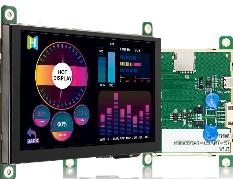
1. Traditional Instrument GUI Development: Common Engineering Bottlenecks
1.1 Limited MCU Processing Resources
Many industrial instruments use microcontrollers optimized for measurement, signal processing, communication, and control.
A digital multimeter, for example, may require its MCU to handle:
- Analog-to-digital conversion
- Measurement calculations
- Calibration
- Input protection monitoring
- Data logging
- Communication
- User interaction
Adding a high-resolution graphical interface increases processing demand.
Animations, anti-aliased text, real-time charts, and graphical transitions require additional CPU cycles and memory bandwidth.
For resource-constrained hardware, these operations can compete with other application tasks.
The problem becomes more significant when a product must maintain predictable measurement timing.
1.2 Framebuffer Memory Requirements
Color graphical interfaces can require substantial framebuffer memory.
For an RGB565 display, each pixel typically occupies 16 bits, or 2 bytes.
The framebuffer memory requirement can be estimated as:
Framebuffer Size = Width × Height × Bytes per Pixel
Consider three common resolutions:
| Resolução | Single RGB565 Framebuffer | Double Buffering |
|---|---|---|
| 320 × 240 | 150 KiB | 300 KiB |
| 480 × 272 | 255 KiB | 510 KiB |
| 800 × 480 | 750 KiB | 1,500 KiB |
These figures exclude graphical assets, software stacks, communication buffers, and application memory.
For example, an 800 × 480 full-color GUI may require external RAM if the MCU lacks sufficient internal memory.
A dedicated display processor can reduce the host MCU’s graphical workload, although the display subsystem still requires suitable memory resources.
1.3 Graphics Library Porting and Driver Integration
Developing an embedded GUI may require engineers to integrate:
- TFT LCD drivers
- Touch controller drivers
- Graphics rendering libraries
- Display interface timing
- Font and image resources
- Operating system components
- Memory management
- Input-event handling
Libraries such as LVGL simplify graphical interface development, but they still require appropriate integration with the hardware platform.
For traditional instrumentation manufacturers, this work may demand embedded GUI expertise beyond the team’s core measurement and control capabilities.
1.4 Linux and Android May Be Unnecessary for Smaller Instruments
Linux and Android platforms provide sophisticated graphical capabilities.
However, they can introduce additional software complexity, memory requirements, boot-time considerations, and system maintenance responsibilities.
For a compact electrical tester displaying numerical readings and a few dynamic charts, a full application processor operating system may be unnecessary.
A microcontroller-based graphical platform or command-driven smart display may offer a more appropriate balance.
Engineering takeaway: The objective is not to eliminate graphics development, but to select an architecture that delivers the required interface without overloading the instrument’s primary measurement controller.
2. What Is an Industrial Smart Display Module?
A smart display module combines a display panel with additional electronics or software capabilities that simplify graphical interface integration.
Depending on its architecture, a module may include:
- TFT LCD or OLED display
- Display driver circuitry
- Dedicated MCU or MPU
- RAM and nonvolatile memory
- Touch controller
- Embedded graphical interface software
- Communication interfaces
- Power management
- Firmware or GUI development tools
However, the term smart display is not standardized.
Different suppliers may use it for substantially different products.
2.1 Three Common Display Architectures
Architecture A: Conventional TFT LCD Module
A standard TFT LCD primarily provides image output.
The host MCU or MPU controls graphics rendering and sends pixel data to the display.
This offers extensive software control but places more responsibility on the host hardware.
Architecture B: Programmable Smart Display
A programmable smart display includes a processing platform capable of running graphical applications locally.
The display processor handles GUI tasks, while the host controller exchanges measurement values, commands, or status information.
The development team may still need to program the graphical application using an embedded graphics framework.
Architecture C: Command-Based Serial HMI Display
A command-based HMI stores graphical elements or interface resources locally.
The host controller sends commands to update values, switch pages, or modify graphical components.
For example, the host MCU may send a measured voltage value to the display rather than rendering the entire screen.
This can substantially simplify communication and reduce the host’s rendering responsibilities.
Smart Display Architecture Comparison
| Característica | Conventional TFT LCD | Programmable Smart Display | Serial HMI Display |
|---|---|---|---|
| Dedicated GUI processor | Usually external | Integrated or associated | Typically integrated |
| GUI rendering location | Host processor | Display subsystem | Display subsystem |
| Host CPU demand | Potentially higher | Reduced for graphics | Often low |
| GUI development | Host application | Embedded GUI application | Vendor tools and commands |
| Interface flexibility | High | High, platform-dependent | Limited by supported commands |
| Display communication | SPI, RGB, MIPI, etc. | Application-dependent | Often UART or another command link |
| Real-time waveform capability | Host-dependent | Hardware-dependent | Protocol and firmware-dependent |
| Engineering control | Extensive | Extensive if software is accessible | Depends on vendor ecosystem |
The best choice depends on the complexity of the interface and the development resources available.
3. How Smart Display Modules Reduce Host MCU Workload
One of the most important advantages of a smart display architecture is the separation of graphical processing from core instrumentation functions.
3.1 Separating Measurement and Display Tasks
Consider a portable measurement instrument.
Its host MCU must continuously acquire sensor data, perform calculations, and maintain communication.
With a conventional graphical display, the same controller may also need to update the framebuffer and manage touchscreen events.
A smart display allows the architecture to be divided into two domains.
Host MCU Responsibilities
- Measurement acquisition
- Signal processing
- Calibration and diagnostics
- Safety and control logic
- Data communication
- Instrument state management
Smart Display Responsibilities
- Graphical interface rendering
- Fonts and icons
- Menus and navigation
- Chart visualization
- Display animation
- Touch event processing
The two subsystems exchange structured information using a defined communication protocol.
This approach can make software development more modular and help engineers maintain predictable measurement behavior.
3.2 Example: Updating a Multimeter Display
In a command-based system, the host might send a logical message containing:
Voltage = 24.85 V
The smart display then updates the corresponding numerical field.
In a conventional framebuffer system, the host may need to redraw the affected screen region or generate new pixel data.
Command-based updates can reduce the amount of data transmitted, especially when the interface consists mainly of numerical fields, indicators, and status icons.
However, not all smart modules accept the same commands.
The protocol, update rate, data format, and GUI capabilities must be confirmed for the selected product.
3.3 Benefits for Real-Time Instrumentation
Separating the GUI from measurement tasks may provide several advantages:
- Reduced graphical CPU workload
- More predictable host processor utilization
- Independent GUI development
- Simplified software maintenance
- Potential reuse of display designs
- More flexible separation of hardware and interface revisions
Nevertheless, the measurement system must still meet its timing, safety, and performance requirements.
A smart display cannot compensate for inadequate host processing capacity in the instrument’s core measurement functions.
4. Lightweight Communication Interfaces: UART, RS485 and CAN
Communication between the host controller and display subsystem is an important architectural decision.
Smart displays may support interfaces such as UART, RS485, CAN, USB, SPI, or Ethernet, depending on their design.
4.1 UART: A Simple Interface for Compact Instruments
UART is commonly used for point-to-point serial communication between embedded controllers.
It can be suitable for instruments that periodically update:
- Measurement values
- Battery indicators
- Warning messages
- Menu settings
- Equipment status
- Configuration parameters
UART requires relatively little host-side hardware complexity.
However, the effective update performance depends on baud rate, protocol overhead, buffering, and message size.
A UART-connected display is not automatically suitable for transferring large volumes of waveform data.
4.2 RS485: Communication for Electrically Demanding Environments
RS485 defines a differential electrical signaling method commonly used in industrial communication systems.
Compared with basic single-ended serial signaling, differential communication can be advantageous for appropriate cable lengths and noise environments.
It is often considered in industrial installations where communication paths are longer or electrical interference is significant.
However, RS485 alone does not define the application protocol.
A smart display using RS485 still requires an agreed message structure, addressing scheme, and error-handling strategy.
4.3 CAN: Integration with Industrial and Vehicle Systems
CAN communication is widely used in automotive and embedded control systems.
Where a smart display supports CAN through suitable hardware and firmware, it may exchange instrument data or status information over a CAN-based architecture.
This can be useful for:
- Vehicle diagnostic equipment
- Mobile machinery
- Embedded control terminals
- Industrial monitoring systems
However, CAN support must be verified for the exact module.
A display equipped with a UART interface cannot be assumed to support CAN without additional hardware or protocol conversion.
Communication Interface Selection
| Interface | Typical Advantage | Key Limitation | Suitable Application |
|---|---|---|---|
| UART | Simple and inexpensive | Limited throughput | Compact meters and basic HMIs |
| RS485 | Differential signaling for industrial links | Requires suitable protocol | Industrial control equipment |
| CAN | Structured communication ecosystem | Requires CAN hardware and protocol integration | Vehicle and machinery instruments |
| SPI | High-speed short-distance peripheral connection | Usually board-level | Embedded displays |
| Ethernet | Higher throughput and networking | Greater system complexity | Advanced industrial terminals |
Engineering recommendation: Select communication interfaces according to update rate, cable length, electrical environment, data volume, and host architecture rather than choosing the interface solely from the display specification.
5. LVGL and TouchGFX: Embedded GUI Platforms for Smart Instrumentation
Modern embedded GUI frameworks can reduce the amount of software that instrument manufacturers need to build from scratch.
Two widely recognized examples are LVGL and TouchGFX.
5.1 LVGL: Flexible Embedded GUI Development
LVGL (Light and Versatile Graphics Library) is an open-source graphics library designed for embedded systems.
It provides graphical components such as:
- Buttons and labels
- Charts and gauges
- Sliders and progress bars
- Images and icons
- Menus and lists
- Animations
- Touch interaction components
LVGL supports different processors and display architectures through appropriate drivers and integration layers.
It can run on resource-constrained embedded systems, although the memory and processing requirements of a particular application depend on resolution, graphical complexity, and performance targets.
For instrumentation OEMs, LVGL can provide a flexible environment for developing custom interfaces.
5.2 TouchGFX: GUI Development for STM32-Based Systems
TouchGFX is a graphical framework developed by STMicroelectronics for STM32 platforms.
It includes TouchGFX Designer, a graphical development tool that supports visual interface design, simulation, and generated application code.
TouchGFX can take advantage of supported STM32 graphical hardware features.
It can be attractive to manufacturers already using compatible STM32 microcontrollers.
However, TouchGFX should not be treated as a universal framework for arbitrary smart display processors.
Platform compatibility must be verified.
5.3 LVGL vs. TouchGFX
| Evaluation Criteria | LVGL | TouchGFX |
|---|---|---|
| Primary positioning | Cross-platform embedded GUI library | STM32-oriented graphical framework |
| Development approach | C-based embedded GUI development | Designer workflow and C++ integration |
| Hardware compatibility | Broad, subject to drivers and resources | Supported STM32 ecosystem |
| Visual GUI tools | Available through compatible tools | TouchGFX Designer |
| Hardware acceleration | Supported where integrated | Supported on appropriate STM32 hardware |
| Typical application | Embedded controllers and smart displays | STM32-based instrumentation |
| Integration responsibility | Application developer or solution provider | Application developer or solution provider |
Both can reduce GUI development effort.
Neither eliminates the need to implement application logic, event handling, communication, and hardware-specific integration.
5.4 Does Every Smart Display Support LVGL or TouchGFX?
No.
Some command-based serial HMI displays use proprietary firmware and configuration tools.
Others provide programmable environments capable of running open-source graphical libraries.
Before purchasing, OEM engineers should confirm whether the module includes:
- A documented LVGL port
- A compatible TouchGFX hardware platform
- Example projects and drivers
- A supported GUI development environment
- Source code or application programming access
- Firmware update procedures
- Long-term software maintenance arrangements
This distinction is essential when comparing quotations from different suppliers.
6. Real-Time Waveforms and Hardware-Accelerated Graphics
Modern test and measurement instruments often require dynamic graphical interfaces.
Examples include oscilloscopes, power analyzers, signal generators, and medical monitoring equipment.
These applications may display:
- Waveform traces
- Oscilloscope grids
- Real-time trend charts
- Animated gauges
- Measurement cursors
- Status indicators
- Alarm notifications
A smart display can reduce the host’s graphics workload, but dynamic visualization requires careful performance engineering.
6.1 Frame Rate vs. Measurement Sampling Rate
An oscilloscope may acquire a large number of samples per second.
However, the display does not need to render every acquired sample as an individual screen update.
For example, the acquisition system may collect thousands or millions of samples while the GUI refreshes at a much lower frame rate.
The instrument’s firmware can process, decimate, or summarize the data before sending it to the display subsystem.
Sampling rate and graphical frame rate are separate engineering parameters.
This distinction is essential for efficient waveform rendering.
6.2 Graphics Acceleration
Some display processors include hardware capabilities such as:
- 2D graphics acceleration
- DMA-assisted memory transfers
- Hardware compositing
- Image scaling
- Efficient framebuffer access
- Supported rendering acceleration
These features can reduce CPU involvement in specific graphical operations.
However, not every smart display contains a GPU.
Even where graphics acceleration is available, its capabilities and software support must be verified.
6.3 Can a Serial Smart Display Render Smooth Waveforms?
It depends on the display’s rendering architecture, communication protocol, and available resources.
Suppose a host sends 500 waveform points per frame at 20 frames per second.
That represents:
500 × 20 = 10,000 points per second
If each point requires four payload bytes, the waveform data alone would require approximately 40,000 bytes per second, before adding framing and protocol overhead.
A conventional 115,200-baud UART link using 8N1 framing has a theoretical data rate of approximately 11,520 payload bytes per second before application overhead.
Consequently, this particular waveform stream would exceed the practical capability of that UART configuration.
Possible alternatives include:
- Reducing transmitted waveform points
- Lowering the update rate
- Increasing communication throughput
- Using an efficient binary protocol
- Rendering waveforms locally
- Using SPI, USB, or another suitable higher-throughput link
- Performing waveform decimation before transmission
Engineering takeaway: A smart display is suitable for real-time measurement visualization only when its rendering capacity and communication bandwidth match the instrument’s data requirements.
7. How Smart Displays Can Reduce Time to Market
For many instrumentation OEMs, software development is a major contributor to product launch schedules.
Traditional GUI development may require multiple engineering activities:
- Display hardware integration
- Display driver development
- Graphics library configuration
- Touchscreen integration
- User-interface programming
- Optimization and testing
- Firmware maintenance
A smart display with appropriate development tools may simplify some of these steps.
7.1 Drag-and-Drop GUI Development
Visual development tools allow engineers to create interface layouts using reusable graphical components.
Depending on the supported platform, developers may configure:
- Screen layouts
- Numeric indicators
- Buttons
- Graphical charts
- Menus
- Page transitions
- Icons
- Alarm indicators
Some tools generate code or produce downloadable GUI resources.
This can simplify interface prototyping and reduce the amount of custom rendering code.
7.2 Parallel Hardware and GUI Development
A modular architecture allows different teams to work simultaneously.
For example:
Measurement Engineering Team
Develops acquisition circuitry, calibration, measurement firmware, and communication protocols.
GUI Development Team
Develops display layouts, visual assets, interaction logic, and touch behavior.
The teams integrate through a defined interface.
This reduces unnecessary coupling between measurement algorithms and graphical presentation.
7.3 Can GUI Development Be Completed in a Few Weeks?
For a limited prototype with a compatible development platform, reusable widgets, stable requirements, and existing examples, a functional GUI may be created within weeks.
However, this should not be presented as a guaranteed production development timeline.
A production-ready industrial instrument may require additional work for:
- Integration testing
- Display performance optimization
- EMC validation
- Environmental qualification
- Localization
- Cybersecurity
- Firmware update validation
- Safety requirements
- Long-term maintenance
Smart displays can shorten some development tasks, but the actual time savings depend on project scope and engineering readiness.
8. Application Scenarios: Smart Displays in Modern Instrumentation
8.1 Portable Oscilloscopes
Portable oscilloscopes require graphical interfaces capable of showing measurement traces, frequency information, channel settings, and waveform analysis results.
A suitable programmable display subsystem may handle the graphical presentation while the primary processor manages data acquisition and signal processing.
Important selection parameters include waveform update rate, memory bandwidth, input latency, and display contrast.
8.2 Digital Multimeters
Modern digital multimeters increasingly incorporate color graphical interfaces.
Typical GUI features may include:
- Large measurement values
- Bar graphs
- Trend plots
- Measurement history
- Battery indicators
- Function selection menus
For these applications, a compact command-driven HMI can be attractive when graphical requirements are moderate and measurement values update relatively slowly.
More sophisticated graphical multimeters may benefit from programmable display platforms.
8.3 Medical Monitoring Equipment
Medical instruments often require clear graphical presentation, alarms, trends, and interactive controls.
Smart display architectures may support interface development and visualization, but medical applications require careful system-level safety engineering.
Alarm handling, patient-critical processing, cybersecurity, and applicable regulatory requirements must not be delegated to an unqualified display subsystem.
The display should be integrated within an appropriately validated medical equipment architecture.
8.4 Intelligent Substation Control Panels
Industrial power systems require interfaces that clearly present electrical measurements, alarms, equipment status, and operational data.
A smart display may act as a local visualization subsystem communicating with a dedicated controller.
Important requirements include:
- EMC immunity
- Operating-temperature range
- Continuous operation
- Communication reliability
- Display readability
- Controlled command authorization
- Appropriate isolation and electrical protection
Where critical switching commands are involved, the system must maintain suitable interlocks and independent protection functions.
8.5 Environmental and Portable Field Instruments
Portable environmental monitoring equipment may display temperature, humidity, pressure, gas concentration, and historical trends.
A smart display can provide a modern interface without requiring the measurement MCU to manage complex graphics.
For battery-powered equipment, developers must also evaluate display power consumption, sleep modes, startup time, and communication efficiency.
9. Smart Display vs. Traditional TFT LCD: OEM Selection Matrix
| Requisito | Recommended Starting Point | Key Reason |
|---|---|---|
| Simple numeric interface | Serial HMI or conventional LCD | Low graphical complexity |
| High customization freedom | Programmable display or host-rendered TFT | Control over UI logic |
| Resource-constrained host MCU | Command-based smart display | Reduced rendering workload |
| High-speed waveform visualization | Programmable display with suitable bandwidth | More flexible data rendering |
| STM32-centered development | TouchGFX-compatible design | Ecosystem integration |
| Cross-platform embedded GUI | LVGL-compatible platform | Broad portability |
| Lowest component cost | Evaluate conventional TFT LCD | Integrated electronics may add cost |
| Short GUI prototyping cycle | Module with mature development tools | Reusable components |
| Industrial 24/7 equipment | Qualified industrial display subsystem | Lifecycle and reliability |
| Long-term software ownership | Open or documented programmable architecture | Reduced platform dependency |
The best solution is the one that matches the actual interface requirements and total engineering cost.
10. Key Considerations Before Selecting an OEM Smart Display Module
A smart display should be evaluated as a complete embedded subsystem rather than a conventional LCD component.
Hardware Specifications
Confirmar:
- TFT LCD or OLED type
- Screen size and resolution
- Brightness and viewing angle
- MCU or MPU model
- RAM and flash capacity
- Framebuffer architecture
- Touchscreen controller
- Supported communication interfaces
Software and GUI Platform
Check:
- LVGL or TouchGFX compatibility, if required
- Proprietary or open development tools
- Available widgets
- Graphics rendering performance
- Source-code access
- Firmware update mechanism
- Version compatibility
- Technical documentation
Instrumentation Performance
Define:
- Required display update rate
- Maximum waveform points per frame
- Host-to-display bandwidth
- Touch response requirements
- Startup time
- Fault recovery behavior
- Consumo de energia
Confiabilidade Industrial
Evaluate:
- Operating and storage temperature
- Mechanical shock and vibration
- EMC immunity
- Display lifetime
- Touchscreen durability
- Long-term component supply
- Firmware maintenance support
Procurement and Lifecycle
For OEM projects, also review:
- Prototype and development kit availability
- Minimum order quantity
- Customization cost
- Tooling requirements
- Product revision control
- Replacement strategy
- Software maintenance responsibilities
An inexpensive smart display may carry higher long-term costs if firmware tools are discontinued or proprietary resources cannot be migrated.
11. Qihantech: OEM/ODM Display Integration for Instrumentation Manufacturers
Developing modern industrial instruments requires coordination between display hardware, embedded electronics, touchscreen functionality, and graphical software.
Qihantech specializes in industrial TFT LCD modules, OLED displays, capacitive touchscreens, and OEM/ODM display integration solutions.
For instrumentation manufacturers, Qihantech’s display and touch capabilities can support the hardware foundation of embedded graphical interfaces.
Industrial TFT LCD and OLED Display Selection
Qihantech offers display solutions for industrial and embedded applications.
Depending on project requirements, engineers can evaluate:
- Tamanho e resolução do ecrã
- Brightness and contrast
- Ângulo de visão
- Operating-temperature range
- Interface elétrica
- Touchscreen compatibility
- Dimensões mecânicas
Display and Touchscreen Customization
Qihantech supports OEM/ODM integration involving:
- Capacitive and resistive touch panels
- Custom cover glass
- Colagem ótica
- Backlight configurations
- FPC and connector customization
- Display interface adaptation
- Mechanical integration requirements
Supporting Embedded GUI Hardware Development
For manufacturers considering a smart display architecture, Qihantech can help evaluate the display and touch hardware requirements of the proposed system.
Important project questions include:
- Will the host MCU render graphics?
- Is a dedicated display processor required?
- Which graphical framework will be used?
- What communication interface is needed?
- What display update rate is necessary?
- Does the module require a specialized controller board?
Specific smart display processing capabilities, LVGL or TouchGFX ports, GPU availability, and supported serial protocols should be confirmed for the proposed hardware configuration.
These are not universal features of every industrial TFT LCD module.
Focus on Core Measurement Technology
For test and measurement OEMs, the goal is to allocate engineering resources efficiently.
A well-designed display architecture allows the product team to prioritize the features that differentiate its equipment:
- Measurement accuracy
- Signal-processing algorithms
- Calibration
- Reliability
- Application-specific functionality
At the same time, a suitable graphical platform helps deliver a modern and intuitive user experience.
Looking for an industrial display solution for your next instrument?
Contact Qihantech to discuss TFT LCD selection, touchscreen integration, display interfaces, mechanical customization, and the hardware requirements of your embedded GUI project.
Website: https://qihantech.com/
12. Frequently Asked Questions (FAQ)
Q1. What is a smart display module?
A smart display module is a display subsystem that includes additional processing, communication, or graphical interface functionality beyond a conventional LCD panel.
Depending on the architecture, it may support local GUI rendering or receive commands from an external controller.
Q2. How does a smart display reduce MCU workload?
A smart display with its own processing resources can handle graphical rendering and interface updates.
The host MCU can transmit measurement values and status commands instead of generating all display pixels.
Q3. What is the difference between a smart TFT LCD and a standard TFT LCD?
A standard TFT LCD primarily receives pixel or display-control signals from external electronics.
A smart TFT LCD typically integrates additional processing or software capabilities for graphical interface management.
The exact definition varies by manufacturer.
Q4. Can smart display modules use LVGL?
Some programmable smart display modules support LVGL when suitable processor resources, display drivers, and software integration are available.
Compatibility must be confirmed for the specific module.
Q5. Is TouchGFX compatible with all smart displays?
No. TouchGFX is primarily designed for supported STM32 platforms.
Compatibility depends on the selected hardware architecture and software environment.
Q6. Can UART smart displays show real-time waveforms?
Yes, some UART smart displays support waveform visualization.
However, practical performance depends on data volume, baud rate, update frequency, and the module’s rendering capabilities.
High-speed waveform applications may require a different interface or processing architecture.
Q7. Do all industrial smart displays include a GPU?
No. Some smart displays use MCU-based software rendering, while others include graphics acceleration.
GPU or hardware acceleration support must be confirmed in the hardware specifications.
Q8. Can RS485 or CAN be used for smart display communication?
Yes, selected modules or associated controller boards may support RS485 or CAN.
However, interface availability and communication protocols vary by product.
Q9. Are smart display modules suitable for medical instruments?
They may be used as interface components in medical instruments when appropriately selected and validated.
The completed medical device must meet its applicable safety, performance, and regulatory requirements.
Q10. How can OEM manufacturers reduce embedded GUI development time?
OEM manufacturers can reduce development effort by selecting suitable display hardware, reusing established graphical frameworks, using available development tools, defining communication protocols early, and separating GUI development from core instrument firmware.
Q11. Should an OEM choose a serial HMI or a programmable smart display?
A serial HMI is often suitable for relatively simple interfaces containing values, menus, and indicators.
A programmable smart display is generally more flexible when the interface requires complex graphics, custom interaction logic, or dynamic visualization.
Q12. What should OEM customers provide when requesting an embedded display solution?
A useful specification includes display size, resolution, host processor, communication interface, GUI complexity, touch requirements, update frequency, temperature range, power limitations, and expected production volume.
Conclusion: Focus on Measurement Algorithms, Deliver a Modern GUI
Modern industrial instruments increasingly require graphical interfaces that present complex measurement information clearly and efficiently.
However, developing an advanced GUI should not necessarily require replacing the entire instrument control architecture.
Smart display modules and embedded GUI platforms can help manufacturers separate display processing from core measurement functions.
Their key benefits may include:
- Reduced graphical workload on the host MCU
- Simplified display integration through defined communication interfaces
- Reusable GUI components and development tools
- Improved software modularity
- Shorter prototyping and integration cycles
- Flexible architectures for future instrument development
Successful implementation still depends on selecting the correct display architecture, communication bandwidth, graphical platform, and environmental specifications.
For instrumentation OEMs, the objective is clear:
Focus engineering resources on measurement accuracy and core algorithms while delivering a modern, responsive, and reliable user interface.
Qihantech provides industrial TFT LCD, OLED, touchscreen, and OEM/ODM display integration solutions to support the development of next-generation instruments.
Explore Qihantech’s display solutions: https://qihantech.com/
 English
 Português
 Français
 Deutsch
 Español
 Русский