An industrial TFT LCD display should be selected around the conditions that can make it fail, not around the specification that looks most impressive in a catalog.
High resolution is useful only if the display starts on a cold morning. Brightness is useful only if the backlight can manage the resulting heat. A wide viewing angle is useful only if the image remains readable in the installed orientation. Even a qualified panel can become unreliable when the enclosure bends its frame, the cable frets under vibration or moisture reaches the connector.
For industrial automation, HMIs, test instruments and outdoor terminals, reliability belongs to the complete display assembly. That assembly includes the TFT cell, backlight, driver IC, FPC, connector, touch panel, adhesive, cover lens, mounting structure and host electronics.
This guide shows how to turn a general request for a “rugged TFT display” into requirements that a manufacturer can design, test and document.
The Short Answer
A reliable industrial LCD module should match five parts of the application:
- The real operating and storage temperature profile
- The required service life and backlight duty cycle
- The viewing geometry and ambient-light conditions
- The mechanical, moisture and contamination environment
- The host interface, mounting envelope and lifecycle plan
Do not approve a display from maximum ratings alone. Ask what the module must do at each limit, how the condition was tested and whether the evidence applies to the exact configuration you will purchase.
What Makes a TFT LCD Display Suitable for Industrial Use?
“Industrial” is not one universal display grade. A factory HMI, portable oscilloscope, EV charger and agricultural controller experience different stresses.
A useful industrial TFT LCD specification starts with the equipment’s work cycle. It describes when the product operates, who views it, how it is mounted and what happens if the display becomes slow, dim or unavailable.
The display is suitable when it can meet agreed optical, electrical and mechanical acceptance criteria throughout that cycle.
Convert Marketing Labels into Evidence
Common labels such as wide temperature, high brightness, long life and vibration resistant are only starting points. Convert each one into a question that can be verified.
| Label | Better purchasing question |
|---|---|
| Wide-temperature LCD | Does the module start, refresh and meet the agreed optical criteria at both temperature limits? |
| Long-life backlight | What lifetime definition, LED current, temperature and brightness endpoint are used? |
| Rugged TFT display | Which shock, vibration, humidity and mounting conditions were tested? |
| Sunlight readable | What is the finished assembly luminance and ambient contrast with the actual cover stack? |
| Industrial interface | Are timing, power sequence, cable length and EMC conditions compatible with the host? |
| Long-term supply | Which parts are controlled, and how are changes and end-of-life events communicated? |
This shift from adjectives to evidence makes supplier comparisons more meaningful.
Begin with a Mission Profile
A mission profile is a concise description of how and where the equipment will be used. It prevents the common mistake of choosing every maximum value independently.
Include:
- Daily operating hours and standby time
- Expected product service life
- Indoor, sheltered outdoor or direct outdoor installation
- Minimum and maximum operating temperature
- Storage and transport temperature
- Humidity, condensation and washdown exposure
- Vibration and shock sources
- Typical viewing distance and angle
- Required screen brightness and dimming behavior
- Touch, glove and cleaning requirements
- Expected production volume and service-parts period
A display used for eight hours per weekday has a different backlight requirement from a process terminal operating continuously. A machine stored at −30°C but powered only above −10°C has a different cold-performance requirement from equipment that must start and operate at −30°C.
Operating Temperature: Define What “Works” Means
An operating range on a datasheet is not a complete description of low- and high-temperature behavior.
At low temperature, liquid-crystal viscosity increases. Pixel transitions become slower, so moving content may smear and screen changes may leave temporary trails. Backlight output, touch response and capacitor behavior can also change.
At high temperature, contrast and color may shift. Polarizers, adhesives, LEDs and flexible circuits experience greater stress. A sealed housing can make the internal temperature substantially higher than the surrounding air, especially when the backlight operates at maximum current.
For a wide temperature LCD, specify which functions must remain within acceptance limits:
- Reliable power-on and initialization
- Readable static image
- Maximum acceptable pixel response time
- Contrast and color stability
- Backlight brightness and uniformity
- Touch operation, if included
- Absence of permanent image defects after recovery
Operating, Storage and Survival Temperature Are Different
Operating temperature describes the range in which the display is intended to function.
Storage temperature describes the unpowered condition. It does not mean the display can operate normally at those limits.
A survival limit may mean only that the module avoids permanent damage after limited exposure. It does not promise image quality or immediate startup.
Ask the supplier to identify which definition applies and to provide the test duration, transition rate, dwell time and recovery criteria.
Use the Temperature at the Display, Not the Weather Forecast
Ambient temperature outside the equipment is only one input. Measure or model the temperature near the TFT, LED backlight and driver electronics.
Solar loading, nearby processors, power supplies and sealed housings can raise internal temperature. At the other extreme, airflow or direct contact with a cold front panel may reduce the display temperature below the nominal enclosure temperature.
Place temperature sensors where the risk exists. A single chamber set point does not reveal gradients inside the product.
Long-Term Reliability Is More Than a Wide Temperature Rating
Temperature range describes an operating envelope. Reliability describes how performance changes with time and stress.
The relevant mechanisms may include LED lumen depreciation, adhesive aging, polarizer degradation, connector fretting, solder fatigue, seal deterioration and changes caused by ultraviolet exposure or humidity.
The correct evidence depends on the application. A portable indoor instrument and a fixed outdoor HMI should not share an identical validation plan.
How to Read a Backlight Lifetime Specification
LED backlight life is often stated as the number of operating hours until brightness falls to a defined percentage of its initial value. A common endpoint is 50 percent, but the exact definition must be confirmed for the quoted module.
Ask for:
- The brightness endpoint used in the lifetime definition
- LED drive current during the estimate or test
- Test or reference temperature
- Whether the value is typical, minimum or calculated
- Dimming profile and duty-cycle assumptions
- Replaceability of the backlight or complete module
A nominal number without those conditions is difficult to use in a service-life calculation.
Estimate the Duty Cycle Before Specifying Lifetime
A simple first estimate is:
Annual backlight hours = operating hours per day × operating days per year × backlight duty factor
If an HMI operates continuously, the backlight may accumulate 8,760 hours in one year. If presence sensing or automatic dimming reduces full-output time, thermal stress and lumen depreciation may also be reduced.
Do not assume that maximum brightness must be used continuously. A controlled dimming strategy can improve indoor comfort, reduce power and support longer backlight life.
Ask for the Reliability Test Matrix
Depending on the product, useful module-level evidence may include:
- High-temperature operating test
- Low-temperature operating test
- High-temperature and high-humidity exposure
- Thermal cycling
- Vibration and mechanical shock
- Electrostatic-discharge evaluation
- Backlight aging
- Connector insertion or cable-flex testing
Test names alone are insufficient. Review the condition, sample size, duration, pass criteria and whether the tested construction matches the proposed bill of materials.
Wide Viewing Angle and Image Stability
An industrial display is often viewed from a standing position, from the side of a machine or from different operator heights. A nominal viewing-angle value does not fully describe what the operator sees.
Contrast can fall asymmetrically as the viewing direction changes. Colors may shift, dark areas may brighten and an image can appear partially inverted. These effects are especially relevant for alarms, trend graphs and controls that use color to communicate state.
IPS and TN: Select from the Installation Geometry
IPS TFT technology generally offers stable color and contrast over wider viewing directions. It is a strong option for shared HMIs, portrait screens and equipment viewed from changing positions.
TN TFT technology can remain appropriate for cost-sensitive or fixed-view applications when the primary viewing direction is known and the user stays within it.
The choice should come from the installed geometry, not from a blanket rule that one technology is always industrial and the other is not.
Verify the Six-O’Clock and Twelve-O’Clock Direction
Some displays have a preferred direction from which contrast remains strongest. A module optimized for six-o’clock viewing may perform poorly when rotated or installed above eye level.
Confirm:
- Landscape or portrait orientation
- Display position relative to the operator
- Expected horizontal and vertical viewing cone
- Whether critical content remains readable at the edges of that cone
- Polarizer behavior when users wear sunglasses
Evaluate the real interface. A color test image can hide problems that become obvious in small gray text or low-contrast status indicators.
Optical Stability Includes the Cover Stack
A touch panel, protective window or optical adhesive changes the finished image. It may reduce brightness, introduce reflection or alter perceived contrast.
Specify whether optical values apply to the bare panel or the completed assembly. For outdoor or high-ambient-light equipment, evaluate the display through the production-intent cover lens and bonding structure.
Vibration and Mechanical Shock Resistance
The TFT glass is only one part of the mechanical system. Most field problems occur at interfaces: the mounting point, bezel, adhesive, cable, connector or solder joint.
Continuous vibration can loosen a connector, wear an FPC at a bend, damage a backlight solder joint or create intermittent contact. A single shock can crack glass, deform a frame or allow the module to strike the enclosure.
Mounting Design Can Create Its Own Failure
Over-constraining a display can transmit housing distortion into the glass. Uneven screws, a warped bezel or compressed foam can produce pressure marks, light leakage, mura or cracking.
Good mounting practice may include:
- Supporting the module at defined structural areas
- Avoiding direct point loads on the active glass
- Controlling screw torque
- Allowing for thermal expansion between materials
- Using suitable pads or gaskets without excessive compression
- Providing strain relief for the FPC and cable
- Keeping the connector accessible for assembly and service
The manufacturer’s drawing should identify keep-out zones, component height and permitted mounting contact areas. Do not derive the housing solely from the visible outline.
Define Shock and Vibration from the Equipment
The requirement should reflect the actual installation: a handheld drop, forklift vibration, compressor resonance, tracked machinery or road vehicle all create different loads.
Specify axes, frequency range, acceleration or displacement, duration, mounting fixture and powered or unpowered state. Inspect function and visual quality after testing, and monitor for intermittent resets or image loss during the test when the application requires operation under vibration.
Passing a generic module test does not certify the final equipment. The enclosure can amplify a frequency that was mild at the test table.
Dust, Moisture and Condensation
A bare TFT LCD module is not an IP-rated enclosure. Dust and water protection come from the front lens, gasket, housing joints, cable exits, vents and assembly process.
Dust can affect connectors and backlight cavities. Moisture can corrode conductors, weaken adhesives and create condensation between optical layers. Conductive contamination may also disrupt a projected-capacitive touch panel.
Design the Front Stack as Part of the Seal
A custom cover lens can create a continuous front surface over the display and touch panel. The lens may include printed borders, mounting adhesive and surface treatments.
Important details include:
- Bond width and adhesive compatibility
- Gasket compression and flatness
- Edge clearance around the display
- Drainage or venting strategy where required
- Cable-exit sealing
- Chemical compatibility with cleaners and process fluids
- Cover-lens deflection under pressure
An IP or IK rating applies to the tested finished enclosure, not to the TFT module or cover glass by itself.
Optical Bonding and Condensation
Optical bonding fills the air gap between the TFT LCD and touch panel or cover lens. It can reduce internal reflections and removes the cavity in which moisture-laden air might condense.
It does not replace enclosure sealing. Moisture can still reach connectors, edges and electronics if the mechanical design is incomplete.
For applications with temperature cycling, test the full assembly for bubbles, edge defects, haze, delamination and image non-uniformity after environmental exposure.
Interfaces: Compatibility Goes Beyond the Connector
Small industrial TFT displays commonly use SPI, MCU, RGB or MIPI DSI. Larger or integrated display systems may use LVDS, eDP, HDMI or a converted interface.
The interface name does not guarantee compatibility. Two modules with RGB or LVDS can differ in timing, voltage, lane mapping, color order, initialization and power sequence.
When selecting a TFT display for HMI equipment, document:
- Host processor and native display peripheral
- Resolution, color depth and target frame rate
- Pixel clock or serial data rate
- Timing polarity and blanking requirements
- Logic and backlight voltages
- Initialization commands
- Power-up and power-down sequence
- Backlight enable and dimming method
- Connector manufacturer and part number
- FPC pinout, length and bend limits
- Maximum cable length and shielding strategy
Prototype the most demanding screen update. A static demonstration does not prove that the interface can support the production HMI at the required speed.
EMC Belongs to the Finished Product
Fast display signals, LED drivers and touch controllers can emit noise. Motors, relays, radios and switching supplies can disturb them.
Signal integrity, grounding, cable routing, shielding, edge rate and power filtering all affect performance. A module-level test report cannot guarantee that the finished machine will meet its applicable EMC standard.
Test the display while the complete equipment operates in worst-case modes: maximum backlight, motor startup, radio transmission, charger connection and active communications.
Mechanical Fit: Same Size Does Not Mean Drop-In Replacement
Two displays with the same diagonal and resolution can have different outer dimensions, thickness, active-area position, mounting features, connector locations and FPC exits.
A small mismatch may require a new bezel, cable or main PCB. It can also shift the image relative to the cover window.
Control these drawing dimensions:
- Module outline and maximum thickness
- Active-area location from mechanical datums
- Viewing-area and cover-window alignment
- Mounting holes, tabs and support surfaces
- Connector position and mating height
- FPC exit direction, length and bend radius
- Component keep-out area
- Touch and cover-lens stack height
Use tolerances rather than nominal dimensions alone. Review tolerance accumulation from the LCD through the bracket, adhesive, cover lens and enclosure.
When a Custom Industrial Display Is the Lower-Risk Option
A standard module is usually the fastest route to a prototype. Customization becomes valuable when the standard module forces compromises into the rest of the product.
Practical semi-custom changes may include:
- A revised FPC length, shape, pinout or connector
- A brighter or differently controlled backlight
- A custom cover lens and printed border
- PCAP or resistive touch integration
- Optical bonding
- A driver or interface-conversion board
- Mechanical brackets or adhesive features
- Firmware or initialization support
The least risky approach is often to preserve the standard TFT cell and customize the surrounding components. A fully custom glass design may require more tooling, time and volume.
Ask which elements remain standard, which become project-specific and which change would trigger requalification.
Supply Continuity Is Part of Reliability
A display can perform perfectly in the field and still stop a product line if its panel, driver IC or backlight becomes unavailable.
Industrial equipment often remains in production and service longer than consumer display platforms. Treat lifecycle planning as a design requirement.
During supplier qualification, ask:
- Is the bill of materials controlled for the quoted module?
- How are product changes communicated?
- What is the process for end-of-life notification?
- Are drawings, initialization files and golden samples revision-controlled?
- Can the mechanical and electrical design accept an alternate panel?
- Which validation must be repeated after a component change?
Write critical notification and supply terms into the agreement for the specific project. Do not rely on a general “long-life” description.
A Failure-Mode-Based Selection Worksheet
This worksheet helps turn application risks into supplier evidence.
| Field risk | Requirement to define | Evidence to request |
|---|---|---|
| Slow or unreadable image in cold conditions | Startup temperature, response-time limit, static readability | Cold-start and low-temperature operating results |
| Overheating in a sealed housing | Internal temperature, luminance duty cycle, power limit | Power data, thermal test with representative assembly |
| Premature dimming | Required brightness after service interval | Backlight lifetime conditions and dimming profile |
| Image inversion at operator position | Installed orientation and viewing cone | Sample viewed with production UI and cover stack |
| Intermittent image under vibration | Equipment vibration profile and mounting method | Test condition, fixture description and powered monitoring |
| Condensation or corrosion | Humidity cycle, sealing and materials | Full-assembly humidity/temperature evaluation |
| Connector or FPC damage | Cable movement, bend radius and strain relief | Drawing limits and assembly validation |
| Host incompatibility | Timing, voltage, initialization and frame rate | Interface specification and working host test |
| Production interruption | Required support period and change process | BOM controls, PCN/EOL terms and alternate strategy |
Questions to Ask an Industrial TFT LCD Manufacturer
Use questions that require a specific answer:
- Which exact display construction was used for the reliability data?
- What must the display do at the operating-temperature limits?
- How is backlight life defined, and under which current and temperature?
- Are luminance and viewing data measured before or after touch and cover integration?
- Which module dimensions and components are revision-controlled?
- What mounting contact areas and mechanical loads are permitted?
- How are interface files, initialization code and firmware revisions controlled?
- What change-notification and end-of-life process applies to this part number?
- Which environmental and EMC tests remain the customer’s responsibility?
- What can be customized without changing the underlying TFT cell?
Clear answers reveal more than a long list of product features.
A Practical Qualification Sequence
1. Review Documents Before Ordering Samples
Check the drawing, timing specification, power sequence, optical conditions, temperature definitions and reliability-test summary. Identify missing information early.
2. Test the Display on the Intended Host
Use the production processor or a representative interface board. Verify initialization, orientation, color order, full-screen updates, sleep and wake behavior, dimming and fault recovery.
3. Install It in a Production-Intent Enclosure
Include the real bracket, gasket, touch panel, cover lens, cables and fasteners. Check active-area alignment, pressure marks, connector access and FPC strain.
4. Exercise the Real HMI
Display small text, gray levels, alarms, moving graphs and the darkest screens. Test from actual operator positions and under the expected lighting.
5. Run Environmental Tests from the Mission Profile
Do not select tests only because they appear in a generic checklist. Use the temperature, humidity, vibration and shock conditions that represent transport, storage and operation.
6. Inspect Recovery and Drift
After exposure, check startup, brightness, uniformity, contrast, color, touch response, bonding, connectors and intermittent faults. Compare results with controlled golden samples.
7. Freeze the Approved Configuration
Record the module revision, driver IC, initialization code, touch firmware, cover drawing, bonding stack and acceptance limits. This becomes the reference for production and future changes.
Recommended Applications
Industrial Automation and PLC HMIs
Machine interfaces often require predictable supply, wide viewing, glove-compatible touch, resistance to electrical noise and clear alarm presentation. Continuous operating hours make backlight duty and thermal design important.
Test and Measurement Instruments
Portable meters and bench instruments need accurate graph and text presentation, compact interfaces and stable behavior during repeated power cycles. Handheld products add drop, cable and battery constraints.
Outdoor Terminals and Energy Equipment
EV chargers, solar controllers and access terminals may combine direct sunlight, high internal temperature, moisture and public use. Brightness, reflection control, sealing and cover-glass durability should be evaluated as one stack.
Transportation and Mobile Machinery
Vehicle and machinery displays experience vibration, voltage disturbances, changing light and large temperature swings. Installation angle, polarized sunglasses and connector retention require early testing.
Medical and Laboratory Equipment
Medical and laboratory HMIs may prioritize cleanability, optical consistency, EMC immunity and long configuration control. Product-specific regulatory and risk-management requirements still apply to the finished device.
How QIHAN Supports Industrial TFT LCD Projects
QIHAN manufactures and supplies small and medium-sized TFT LCD modules from 0.96 to 15.6 inches for industrial, embedded and HMI applications.
QIHAN’s published capabilities include selected wide-temperature display solutions, high-brightness and transflective options, TFT and capacitive-touch optical bonding, custom cover glass, touch integration, FPC and interface customization, driver boards and interface conversion.
The company’s published production and validation resources include TFT panel processing, backlight assembly, CTP assembly, high- and low-temperature testing and vibration testing.
Published wide-temperature examples extend from −30°C to +85°C. This range should not be assumed for every module or complete bonded assembly. The exact operating behavior, test condition and available construction must be confirmed for the selected part number.
Frequently Asked Questions
What is the difference between a commercial and industrial TFT LCD?
An industrial module is selected and controlled for a defined operating environment, lifecycle and validation plan. Relevant differences may include temperature behavior, backlight life, mechanical construction, component control and supplier documentation. The word “industrial” alone does not prove those attributes.
Does a −30°C to +85°C rating mean the display looks normal across the full range?
Not necessarily. The range may permit operation while response time, brightness, contrast or touch behavior changes. Define acceptance limits and ask how the exact module performs at each endpoint.
Is IPS always required for an industrial HMI?
No. IPS is valuable when users view the display from multiple directions or stable color is important. A TN display can be appropriate when the viewing position is controlled and its preferred direction matches the installation.
How should I compare backlight lifetime?
Compare the brightness endpoint, LED current, test temperature and whether the value is typical or minimum. Then relate operating hours and dimming duty to the product’s service life.
Does a TFT module have an IP rating?
Normally, the module alone does not establish an enclosure IP rating. The cover lens, gasket, housing, cable exits and complete assembly must be designed and tested together.
Can two displays with the same size and resolution be interchangeable?
Not automatically. Outline, thickness, active-area position, connector, pinout, voltage, timing, initialization, brightness and viewing direction may differ.
Can QIHAN customize a small industrial TFT display?
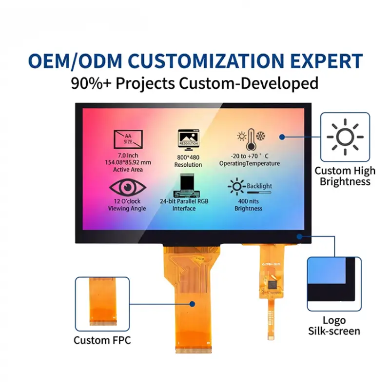
QIHAN offers project-based customization including FPC, interfaces, backlights, touch panels, cover glass, optical bonding, driver boards and mechanical adaptation. Feasibility and order requirements depend on the selected platform.
Specify the Risk Before You Specify the Display
The most reliable industrial TFT LCD is not necessarily the model with the widest temperature range or highest brightness. It is the display whose documented behavior matches the equipment’s mission profile and whose integration risks have been tested in the finished system.
Define what failure means. Measure the real temperature. Confirm the operator’s viewing geometry. Design the mounting and cable before tooling the enclosure. Record interface and component revisions. Plan for supply changes while alternatives still exist.
QIHAN can help evaluate a small-size industrial LCD module, mechanical adaptation, touch and cover stack, backlight, bonding and interface solution for your application.