
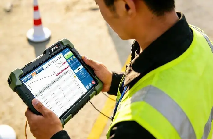
Imagine an electrical engineer inspecting a solar photovoltaic (PV) installation under direct sunlight. The handheld tester is operating correctly, but the screen is difficult to read because sunlight reflections overwhelm the measurement values.
The same problem affects technicians using optical time-domain reflectometers (OTDRs), portable oscilloscopes, environmental monitoring instruments, and industrial diagnostic devices.
For field instrumentation, display readability is not simply a matter of visual comfort. Engineers need to identify measurement values, recognize warning indicators, interpret waveforms, and navigate instrument settings quickly and accurately.
A display that works perfectly indoors may become almost unreadable outdoors, even when its resolution and color performance are excellent.
This is why sunlight-readable TFT LCD technology has become an important design consideration for manufacturers of portable industrial equipment.
However, increasing display brightness is only part of the solution.
Outdoor readability depends on the combined performance of the LCD panel, LED backlight, touchscreen, cover glass, optical bonding materials, and anti-reflective surface treatments.
This article explains the engineering principles behind sunlight readability and compares four practical solutions:
- High-brightness LED backlighting
- Anti-glare, anti-reflection, and anti-fingerprint coatings
- Optical bonding with OCA or LOCA
- Transflective LCD technology
It also provides a selection framework for OEM manufacturers developing outdoor measurement instruments.
1. The Physics of Sunlight Readability: Brightness, Reflection, and Ambient Contrast
A common mistake in display selection is assuming that a higher brightness specification always guarantees better outdoor visibility.
In reality, sunlight readability depends on how much useful display light reaches the viewer compared with how much ambient light is reflected toward the viewer.
Three factors are particularly important.
1.1 Display Brightness: Understanding Nits
Display brightness is commonly specified as luminance, measured in candelas per square meter (cd/m²), also known as nits.
One nit equals one cd/m².
A conventional indoor TFT LCD may have a typical luminance of approximately 250–500 nits.
High-brightness industrial TFT LCD modules may offer substantially higher output, with configurations around 1,000–2,000 nits or more available in the broader display market.
For outdoor instruments, higher luminance helps the emitted image compete with strong reflected ambient light.
However, the luminance specified in a TFT LCD datasheet may refer to the bare display module rather than the finished instrument.
Additional layers can reduce the light reaching the operator.
These may include:
- Touch sensor layers
- Защитное стекло
- Optical adhesives
- Polarizers
- Surface coatings
Engineering recommendation: When specifying an outdoor instrument display, evaluate luminance at the outer surface of the completed display assembly, not only the bare TFT module.
1.2 Surface Reflection: Why Bright Screens Still Look Washed Out
Every optical boundary can reflect part of the incoming light.
When sunlight reaches a display assembly, reflections can occur at interfaces involving:
- Air and protective cover glass
- Cover glass and internal air gaps
- Touch sensor substrates
- LCD polarizers
- Other optical layers
For an uncoated glass-to-air interface with a refractive index of approximately 1.5, the normal-incidence Fresnel reflection is roughly 4%.
A display with multiple reflective interfaces can therefore suffer significant glare.
In bright sunlight, reflected light increases the apparent luminance of dark screen regions.
As black areas become brighter, the difference between light and dark information decreases.
The result is a washed-out display.
This explains why two TFT LCDs with identical brightness ratings can perform differently outdoors.
A lower-brightness display with a carefully designed optical stack may provide better readability than a brighter module with excessive reflections.
1.3 Ambient Contrast Ratio: The Real Measure of Outdoor Readability
Contrast ratio describes the difference between the luminance of bright and dark image regions.
Indoor display specifications often report contrast under controlled lighting conditions.
However, outdoor measurement instruments must be evaluated under significant ambient illumination.
A simplified ambient contrast ratio (ACR) can be expressed as:
ACR = (Lwhite + Lreflected) / (Lblack + Lreflected)
Where:
- Lwhite = luminance of a white display region
- Lblack = luminance of a black display region
- Lreflected = ambient light luminance reflected toward the viewer
This simplified expression assumes the same additive reflected luminance in both display states.
For example, consider a display with:
- White luminance: 1,000 nits
- Black luminance: 1 nit
- Reflected ambient luminance: 200 nits
The resulting ambient contrast ratio is approximately:
ACR = (1,000 + 200) / (1 + 200) ≈ 5.97:1
Now imagine that improved optical treatments reduce reflected luminance to 50 nits.
The ambient contrast becomes:
ACR = (1,000 + 50) / (1 + 50) ≈ 20.59:1
These hypothetical calculations demonstrate an important principle:
Reducing reflected light can improve outdoor contrast without increasing LED backlight power.
Real-world evaluation must also account for reflection geometry, diffuse and specular reflection, measurement conditions, and the complete optical structure.
What Matters Most for Outdoor Readability?
| Параметр | What It Measures | Engineering Significance |
|---|---|---|
| Brightness (nits) | Emitted luminance | Helps overcome reflected ambient light |
| Reflectance (%) | Portion of incident light reflected | Influences glare and image washout |
| Ambient Contrast Ratio | Visible contrast under ambient illumination | Better represents outdoor readability |
| Optical Transmission | Light passing through the assembled optical stack | Affects finished luminance |
| Угол обзора | Display appearance across observation directions | Important for handheld operating positions |
| Потребляемая мощность | Energy required to operate the display | Critical for battery-powered instruments |
| Thermal Performance | Temperature behavior under operating conditions | Important for outdoor reliability |
2. Solution One: High-Brightness TFT LCD Backlight Design
For many outdoor field instruments, a high-brightness TFT LCD is the most straightforward way to improve display visibility.
A conventional TFT LCD uses an LED backlight to illuminate the liquid crystal panel.
By modifying the backlight design, manufacturers can increase the amount of light reaching the viewer.
2.1 How High-Nits LED Backlights Work
High-brightness TFT modules may use:
- High-efficiency LED light sources
- Optimized LED arrangements
- Improved light-guide plates
- Reflective films
- Brightness-enhancement films
- Diffusion layers
- Improved backlight driving circuits
The objective is to achieve sufficient luminance and acceptable uniformity while controlling electrical power and heat generation.
For OEM instrument manufacturers, selecting an appropriate backlight is a trade-off between optical output, battery life, temperature, thickness, and cost.
2.2 Is 1,000 Nits Enough for Direct Sunlight?
There is no universal brightness value that guarantees sunlight readability.
The required luminance depends on:
- Direct sunlight versus open shade
- Viewing angle
- Cover-glass reflectance
- Оптическое склеивание
- Display contrast
- User-interface colors
- Screen size
- Enclosure shading
The following ranges can serve as preliminary engineering references.
| Operating Environment | Initial Brightness Evaluation Range | Design Considerations |
|---|---|---|
| Bright indoor environment | 400–700 нит | Reflections from overhead lighting |
| Outdoor shaded areas | 500–800 нит | Surface reflections and battery life |
| Intermittent direct sunlight | 800–1,200 nits | AR treatment and bonding |
| Frequent outdoor sunlight | 1 000–1 500 нит | Contrast, thermal management and power |
| Prolonged severe sunlight | 1,500–2,000+ nits | Advanced optical design and system validation |
These values are preliminary design ranges, not performance guarantees. Required brightness must be confirmed through application-specific testing.
For example, a handheld OTDR used outdoors may achieve acceptable readability with a 1,000-nit bonded TFT LCD and an optimized cover lens.
Another instrument with a highly reflective cover glass may remain difficult to read despite having a 1,500-nit panel.
2.3 The Trade-Off Between Brightness and Battery Life
Increasing LED backlight output generally requires more electrical power.
This is particularly important for portable measurement instruments.
A handheld tester may rely on a rechargeable battery that must also power:
- Measurement circuitry
- Main processor
- Wireless communication
- Sensors
- Data storage
- User-interface electronics
If the display continuously operates at maximum brightness, available operating time may decrease substantially.
Engineers should therefore evaluate actual backlight power consumption rather than relying on nominal brightness specifications alone.
2.4 Thermal Management for High-Brightness Displays
LED backlights convert some electrical energy into heat.
At elevated temperatures, LED efficiency, luminance stability, and lifetime can be affected.
Outdoor instruments also absorb solar radiation through their enclosures and display surfaces.
A black instrument housing exposed to direct sunlight may become substantially hotter than the surrounding air.
Recommended thermal measures include:
Efficient Backlight Selection
Use suitable LED configurations and optical films to achieve the required luminance without unnecessary power consumption.
Adaptive Brightness Control
Use an ambient light sensor to reduce backlight intensity when maximum brightness is unnecessary.
Thermal Feedback
Use temperature sensing to regulate backlight output when the display approaches its thermal limits.
Mechanical Heat Dissipation
Consider heat conduction paths, enclosure materials, and internal component placement.
Temperature Qualification
Test the display inside the finished instrument under expected operating conditions.
For field instruments, a high-brightness display should be evaluated as an electrical and thermal subsystem rather than merely an LCD specification.
3. Solution Two: AG, AR, and AF Coatings for Outdoor Display Readability
Surface treatments are an important part of a sunlight-readable display design.
Three common technologies are anti-glare (AG), anti-reflection (AR), and anti-fingerprint (AF) treatments.
Each addresses a different problem.
3.1 Anti-Glare (AG): Reducing Distracting Reflections
Anti-glare treatments modify the cover-glass surface to scatter incoming light.
Instead of producing a concentrated mirror-like reflection, an AG surface distributes reflected light across a wider range of angles.
This can improve viewing comfort when instruments are exposed to strong directional reflections.
К типичным областям применения относятся:
- Portable electrical testers
- Outdoor environmental analyzers
- Промышленные панели управления
- Vehicle diagnostic devices
However, excessive surface haze may reduce perceived sharpness.
For instruments displaying small numbers or fine waveform traces, engineers should evaluate AG haze carefully.
3.2 Anti-Reflection (AR): Minimizing Surface Reflectance
Anti-reflection coatings reduce reflected light at optical surfaces.
They generally use carefully designed thin-film structures to control optical interference.
AR coatings can improve outdoor contrast by reducing the intensity of reflections reaching the viewer.
For handheld measurement instruments, this is particularly valuable when the operator must read small text or identify detailed graphical information.
The effectiveness of an AR coating depends on:
- Coating design
- Wavelength
- Angle of incidence
- Substrate material
- Durability requirements
A low reflectance measured under one lighting condition does not necessarily represent performance under every viewing angle.
3.3 Anti-Fingerprint (AF): Maintaining Optical Clarity
Portable instruments are frequently handled by technicians.
Fingerprints, skin oils, dust, and other contaminants may reduce visual clarity.
AF coatings typically provide an oleophobic surface that reduces the adhesion of fingerprints and makes cleaning easier.
They do not directly replace AR or AG treatments.
However, they can help maintain a clean viewing surface during repeated field operation.
3.4 Comparing AG, AR, and AF Technologies
| Technology | Main Function | Key Advantage | Engineering Trade-Off |
|---|---|---|---|
| AG | Scatters reflected light | Reduces distracting glare | Excessive haze may affect clarity |
| AR | Reduces optical reflections | Improves outdoor contrast | Coating performance and durability vary |
| AF | Reduces fingerprint adhesion | Improves cleaning and usability | Does not substantially replace reflection control |
| AG + AR | Combines reflection-management methods | Can improve outdoor viewing | Requires balanced optical design |
| AR + AF | Reflection reduction and cleanability | Suitable for frequently used instruments | Requires coating compatibility |
Engineering recommendation: For outdoor instruments showing detailed measurement values, AR coating is often worth evaluating first. AG may be added when directional glare is problematic, while AF is useful for touch-operated equipment.
4. Solution Three: Optical Bonding for Sunlight-Readable TFT LCDs
Optical bonding is one of the most effective techniques for reducing internal reflections in a display assembly.
Traditional display structures often include an air gap between the TFT LCD and the touchscreen or protective cover glass.
When light passes through multiple air-to-glass interfaces, reflections can reduce image contrast.
Optical bonding replaces the air gap with a transparent adhesive.
4.1 How Optical Bonding Reduces Reflection
The physical principle is based on refractive-index matching.
For normal incidence, the approximate Fresnel reflectance at an interface is:
R = ((n₁ − n₂) / (n₁ + n₂))²
Where:
- n₁ is the refractive index of the first material.
- n₂ is the refractive index of the second material.
- R is the fraction of light reflected at the interface.
For an air-to-glass interface with refractive indices of approximately 1.0 and 1.5:
R ≈ 4%
When the air gap is replaced with an optical adhesive having a refractive index close to that of glass, reflection at the bonded interface can be substantially reduced.
This helps preserve visible contrast under bright ambient conditions.
4.2 Can Optical Bonding Reduce Reflection from 13.5% to 0.2%?
Published optical bonding examples have illustrated reductions in total reflection from approximately 13.5% for a particular air-bonded construction to around 0.2% for an optimized bonded construction.
However, these figures describe specific optical designs and measurement conditions.
They should not be interpreted as universal optical bonding performance.
In practice, total display reflectance depends on:
- External cover-glass reflectance
- AR coating
- Touch sensor materials
- Optical adhesive
- LCD polarizer
- Internal optical interfaces
- Viewing angle and measurement geometry
Optical bonding can substantially reduce reflections from internal air gaps, but it does not automatically eliminate reflection from the external glass surface.
For OEM equipment, reflectance should be measured on the finished optical assembly.
4.3 OCA vs. LOCA Optical Bonding
Two commonly used optical bonding materials are OCA and LOCA.
OCA — Optically Clear Adhesive
OCA is generally supplied as a transparent adhesive film.
It can support controlled adhesive thickness and consistent bonding in compatible manufacturing processes.
LOCA — Liquid Optically Clear Adhesive
LOCA is applied in liquid form and cured after assembly.
It can be useful for selected geometries and manufacturing processes.
Both methods require careful control of bubbles, contamination, stress, material compatibility, and curing or lamination conditions.
4.4 Additional Benefits of Optical Bonding
Beyond sunlight readability, optical bonding can provide other benefits.
Reduced Internal Condensation Risk
Eliminating the air gap reduces the opportunity for moisture condensation between bonded optical layers.
Improved Optical Integration
The bonded structure may reduce internal reflections and improve perceived image clarity.
Reduced Parallax
Removing the air gap can reduce the apparent separation between the display image and touch surface.
Potential Mechanical Benefits
Appropriate bonding may reduce relative movement between layers, although impact and vibration performance must still be verified.
Optical bonding is not equivalent to waterproofing or impact certification.
4.5 When Is Optical Bonding Worth the Additional Cost?
Optical bonding is particularly worth evaluating when:
- Instruments are regularly used in direct sunlight.
- Detailed graphical information must remain visible.
- The display includes a touchscreen and protective cover glass.
- The equipment experiences significant temperature changes.
- Internal condensation is a concern.
- A higher-brightness backlight would create excessive heat or power demand.
For some outdoor instruments, reducing reflection through bonding may be more efficient than increasing LED backlight brightness alone.
5. Solution Four: Transflective TFT LCD Technology for Battery-Powered Instruments
High-brightness backlights are effective, but they consume energy.
For battery-powered field instruments, engineers may need a display that remains visible outdoors without continuously operating a high-power backlight.
This is where transflective LCD technology becomes relevant.
5.1 What Is a Transflective TFT LCD?
A transflective LCD combines transmissive and reflective operating characteristics.
In transmissive mode, light from the internal backlight passes through the LCD.
In reflective operation, a portion of the incoming ambient light is reflected back through the LCD structure to illuminate the image.
This allows sunlight to become a useful source of illumination rather than only an obstacle.
5.2 Transmissive vs. Reflective vs. Transflective LCDs
| Особенность | Transmissive TFT LCD | Светоотражающий ЖК-дисплей | Трансфлективный ЖК-дисплей |
|---|---|---|---|
| Primary illumination | LED backlight | Ambient light | Ambient light and backlight |
| Direct sunlight | Requires optimized high-brightness design | Often favorable | Often favorable |
| Indoor low-light readability | Good with backlight | Limited without front lighting | Good with backlight |
| Backlight power | Required for normal viewing | Usually unnecessary | Can be reduced outdoors |
| Color appearance | Typically strong | Depends on design | May show color/contrast trade-offs |
| Battery efficiency outdoors | Depends on backlight demand | Often strong | Often strong |
| Industrial availability | Broad | Application-dependent | More limited and specialized |
5.3 Why Transflective Displays Can Reduce Power Consumption
In bright sunlight, the reflective portion of a transflective display helps illuminate the screen.
The backlight can potentially be dimmed or switched off while maintaining usable readability.
This is attractive for instruments such as:
- Handheld environmental monitors
- Portable navigation and surveying equipment
- Battery-powered industrial sensors
- Selected outdoor measurement devices
- Portable diagnostic terminals
The actual power savings depend on the display design, ambient lighting, and operating mode.
5.4 Limitations of Transflective LCD Technology
Transflective displays are not universally superior to high-brightness transmissive TFT LCDs.
Potential disadvantages include:
Limited Module Availability
Available sizes, resolutions, interfaces, and touchscreen configurations may be more restricted.
Optical Trade-Offs
Color saturation and perceived contrast may vary between reflective and backlit operation.
Customization Cost
Specialized panels may involve different pricing or supply considerations.
Application-Specific Readability
The final interface must still be evaluated in direct sunlight, shade, and darkness.
Engineering recommendation: Consider transflective TFT technology when battery runtime is a major constraint and the instrument must operate frequently in bright natural light.
6. High-Brightness TFT vs. Transflective LCD: Which Is Better?
The right choice depends on application priorities.
| Selection Criteria | High-Brightness TFT LCD | Transflective TFT LCD |
|---|---|---|
| Full-color graphical interface | Often advantageous | Depends on module |
| High-resolution waveform display | Broad module options | Selection may be limited |
| Direct sunlight visibility | Strong with suitable bonding and AR | Benefits from ambient reflection |
| Battery runtime | Higher backlight demand | Potentially lower demand outdoors |
| Indoor use | Отлично | Good with backlight |
| Optical customization | Broad options | Depends on module |
| Module availability | Generally broad | More specialized |
| High ambient temperature | Requires thermal management | Lower backlight demand may help |
| OEM integration | Often straightforward | Requires module-specific evaluation |
For a full-color OTDR displaying detailed trace information, a high-brightness IPS TFT LCD with optical bonding and AR cover glass may be an effective starting point.
For a battery-powered environmental measuring instrument displaying relatively simple graphical data, a transflective LCD may offer advantages in power consumption.
7. Application-Based Recommendations for Field Instruments
7.1 Optical Time-Domain Reflectometers (OTDRs)
OTDRs are used for fiber-optic cable testing and troubleshooting.
Technicians frequently work outdoors and need to interpret detailed waveform traces, distance markers, and measurement results.
Recommended starting configuration:
- High-brightness IPS TFT LCD
- Approximately 1,000–1,500 nits for evaluation
- Оптическое склеивание
- Low-reflection cover glass
- Suitable viewing angles
- Adaptive brightness control
The actual brightness requirement should be confirmed using realistic trace screens under outdoor conditions.
7.2 Solar PV Testing Instruments
Solar PV testers are often used under intense sunlight near reflective panels.
In addition to display brightness, solar exposure can increase the instrument’s internal temperature.
Recommended starting configuration:
- Промышленный TFT-ЖК-дисплей высокой яркости
- Optical bonding where beneficial
- AR-treated cover glass
- Temperature-aware brightness control
- Suitable thermal dissipation
- Industrial operating-temperature qualification
Engineers should test the complete instrument under representative solar loading.
7.3 Portable Environmental Monitoring Devices
Handheld environmental instruments may operate for extended periods on battery power.
Their interfaces often contain numerical readings, simple charts, and status indicators.
Recommended starting configuration:
- Efficient high-brightness TFT or suitable transflective LCD
- Automatic backlight dimming
- Low-reflection optical stack
- Battery-runtime validation
- Appropriate outdoor sealing
Transflective technology is especially worth evaluating when extended battery life is more important than maximum color saturation.
7.4 Outdoor Electrical Inspection Equipment
Electrical testers used for outdoor maintenance may be operated in bright sunlight, with gloves, or under changing weather conditions.
Recommended starting configuration:
- Sunlight-readable TFT LCD
- AR/AF cover-glass treatment
- Optical bonding where justified
- Glove-compatible touch functionality if required
- Конструкция, рассчитанная на широкий диапазон температур
- Robust enclosure integration
Where a touchscreen is used, touch performance must be validated with the finished cover-glass assembly.
8. Outdoor Display Decision Matrix: Performance, Power and Budget
| OEM Project Requirement | Recommended Display Strategy | Main Trade-Off |
|---|---|---|
| Budget-sensitive outdoor instrument | Moderate high brightness + AR | Limited severe-sun margin |
| Regular outdoor testing | 1,000–1,500-nit TFT + bonding + AR | Increased integration cost |
| Continuous direct sunlight | High-brightness TFT + optimized optical stack | Heat and power |
| Long battery runtime | Transflective TFT where suitable | Module and color limitations |
| Detailed waveform GUI | High-brightness IPS TFT | Backlight consumption |
| Touch-operated field instrument | Bonded TFT + AR/AF cover | Cost and touch-stack complexity |
| Extreme temperature variation | Qualified TFT + thermal control | Engineering and validation effort |
The most cost-effective solution is not necessarily the display with the highest brightness rating.
Reducing reflection, optimizing interface design, and controlling backlight power may produce a better overall result.
9. Engineering Checklist for Selecting a Sunlight-Readable TFT LCD
Before selecting an outdoor display module, OEM engineers should define the following specifications.
Optical Performance
- Размер и разрешение экрана
- Required luminance at the finished cover surface
- Maximum acceptable reflectance
- Ambient contrast requirements
- Viewing angle
- Color and waveform readability
- AR/AG/AF coating requirements
- Optical bonding preference
Environmental Conditions
- Direct sunlight exposure
- Ambient operating temperature
- Solar heating of the enclosure
- Humidity and condensation
- Water and dust exposure
- Temperature cycling
- Воздействие ультрафиолета
Electrical Requirements
- Display interface
- Power supply voltage
- Maximum backlight power
- Brightness dimming range
- Ambient light sensor integration
- Thermal protection strategy
- Electromagnetic compatibility requirements
Mechanical Integration
- Display outline dimensions
- Touchscreen dimensions
- Cover-glass thickness
- Optical bonding stack
- FPC orientation and connector
- Mounting constraints
- Enclosure shading and sealing
Procurement and Lifecycle
- Prototype availability
- OEM customization requirements
- Expected annual production volume
- Product lifecycle
- Component supply continuity
- Backlight lifetime definition
- Optical and environmental test documentation
A well-defined request for quotation helps display suppliers recommend a suitable solution without unnecessary overengineering.
10. How to Validate Sunlight Readability Before Mass Production
Laboratory brightness measurements are necessary, but they do not fully predict outdoor readability.
OEM manufacturers should evaluate production-intent display assemblies under representative field conditions.
Step 1: Measure Finished-Surface Luminance
Measure brightness through the final cover glass and touchscreen assembly.
Record the measurement conditions and backlight settings.
Step 2: Evaluate Reflected Light
Assess specular and diffuse reflections under the expected lighting geometry.
Where relevant, measure display reflectance and calculate ambient contrast using an agreed method.
Step 3: Test the Actual User Interface
Use real measurement screens rather than promotional images.
Include small numerical values, warning indicators, graphs, and fine waveform traces.
Step 4: Test Under Multiple Outdoor Conditions
Evaluate direct sunlight, open shade, overcast daylight, and relevant viewing angles.
Step 5: Validate Thermal Performance
Operate the instrument in its final enclosure under expected solar and electrical loading.
Check whether brightness control or thermal protection reduces readability during prolonged use.
Step 6: Evaluate Power Consumption
Measure display power at typical indoor and outdoor brightness settings.
Confirm battery runtime under representative use.
Step 7: Verify Long-Term Reliability
Evaluate backlight aging, optical adhesive stability, cover-glass durability, and performance across the specified operating-temperature range.
This process helps prevent costly redesigns after product launch.
11. Qihantech: High-Brightness TFT LCD and Optical Integration for OEM Field Instruments
Selecting a sunlight-readable display requires more than choosing an LCD panel with a high luminance specification.
For industrial instrument manufacturers, the complete optical assembly must balance readability, power consumption, environmental reliability, mechanical integration, and long-term availability.
Qihantech specializes in industrial TFT LCD displays, OLED displays, and capacitive touchscreen solutions for OEM/ODM applications.
Its display solutions support applications including portable measurement instruments, industrial control equipment, outdoor terminals, and embedded electronic systems.
High-Brightness Industrial TFT LCD Solutions
Qihantech provides selected high-brightness TFT LCD configurations for applications requiring improved outdoor visibility.
Available options and project specifications should be confirmed according to display size, resolution, operating temperature, and interface requirements.
Optical Bonding and Cover-Glass Customization
Qihantech supports optical bonding and custom cover-glass integration for industrial display assemblies.
Depending on project requirements, solutions may incorporate:
- OCA or LOCA optical bonding
- Anti-glare surface treatments
- Anti-reflection coatings
- Anti-fingerprint treatments
- Customized cover-glass dimensions
- Capacitive touchscreen integration
OEM/ODM Display Integration
Qihantech’s customization capabilities include evaluation of:
- Display sizes and resolutions
- Backlight brightness
- Electrical interfaces
- FPC and connectors
- Touchscreen structures
- Mechanical integration
- Driver-board requirements
- Environmental specifications
For battery-powered outdoor equipment, suitable transflective TFT options may also be evaluated according to module availability and project requirements.
Work with Qihantech on Your Outdoor Instrument Display
Whether developing an OTDR, solar PV tester, environmental monitoring device, or portable electrical instrument, early optical design decisions can significantly influence final product performance.
Qihantech can work with OEM/ODM customers to review brightness targets, touch integration, cover-glass construction, and environmental requirements.
Looking for a sunlight-readable TFT LCD for your next field instrument?
Contact Qihantech to discuss high-brightness TFT displays, optical bonding, anti-reflective cover glass, and customized display integration.
Website: https://qihantech.com/
12. Frequently Asked Questions (FAQ)
Q1. What is a sunlight-readable TFT LCD?
A sunlight-readable TFT LCD is a display system designed to maintain usable image contrast under strong ambient illumination.
It may combine high-brightness backlighting, low-reflection optical layers, anti-reflective coatings, and optical bonding.
Q2. Is a 1,000-nit TFT LCD bright enough for outdoor use?
A 1,000-nit display may be suitable for some outdoor applications, especially when paired with optical bonding and a low-reflection cover lens.
However, severe direct sunlight may require higher luminance or a different optical design.
Q3. What is the difference between anti-glare and anti-reflection coatings?
Anti-glare treatments scatter reflected light to reduce distracting reflections.
Anti-reflection coatings reduce the amount of light reflected from an optical surface.
The best option depends on viewing conditions and display clarity requirements.
Q4. Does optical bonding make an LCD sunlight readable?
Optical bonding can improve sunlight readability by reducing internal reflections.
However, it does not automatically guarantee readable performance. Display brightness, external reflections, and ambient contrast remain important.
Q5. Can optical bonding reduce reflection to less than 0.2%?
Certain optimized optical configurations may achieve extremely low reflection values under defined conditions.
However, a sub-0.2% reflectance specification cannot be assumed for every bonded display assembly.
It requires verification of the exact optical stack and measurement conditions.
Q6. Is OCA or LOCA better for industrial TFT LCD bonding?
Both technologies can provide effective optical bonding.
Selection depends on display construction, adhesive compatibility, production process, environmental requirements, and manufacturing cost.
Q7. What is a transflective TFT LCD?
A transflective TFT LCD combines reflective and transmissive illumination characteristics.
It can use ambient light outdoors and a backlight in low-light conditions, making it useful for selected battery-powered equipment.
Q8. Are transflective displays better than high-brightness TFT LCDs?
Not universally.
Transflective displays can offer power advantages in bright ambient environments, while high-brightness transmissive TFT LCDs often provide broader module options and strong full-color image performance.
Q9. How does high brightness affect LCD lifetime?
Higher LED drive levels can increase power consumption and thermal stress.
Backlight lifetime depends on LED design, operating current, temperature, and the manufacturer’s specified aging conditions.
Appropriate dimming and thermal management can help reduce unnecessary stress.
Q10. Can Qihantech customize sunlight-readable displays for portable instruments?
Qihantech offers OEM/ODM display customization, including selected high-brightness TFT LCDs, touch integration, optical bonding, cover-glass treatments, and interface customization.
Actual specifications and supported configurations should be confirmed for the individual project.
Conclusion: Sunlight Readability Requires Complete Optical System Design
Developing a reliable outdoor instrument display requires balancing brightness, reflection, contrast, electrical power, and thermal performance.
Increasing TFT LCD brightness can improve visibility, but it is not always the most efficient solution.
Four technologies play important roles:
- High-brightness LED backlights provide additional luminance under strong ambient lighting.
- AG, AR, and AF treatments manage glare, reflections, and surface contamination.
- Оптическое склеивание reduces internal reflections and improves optical integration.
- Transflective LCD technology uses ambient light to support outdoor readability with potentially lower backlight power.
For portable instruments, the most suitable configuration depends on display content, sunlight exposure, battery capacity, enclosure conditions, and total project cost.
A high-brightness IPS TFT LCD with optical bonding may be well suited to a waveform-intensive OTDR, while a transflective display may be a practical option for a low-power environmental monitoring device.
The best sunlight-readable display is not necessarily the brightest one. It is the one that delivers sufficient outdoor contrast with acceptable power consumption, thermal performance, and lifecycle cost.
Qihantech provides industrial TFT LCD, touchscreen, optical bonding, and OEM/ODM display integration solutions for equipment manufacturers.
Explore Qihantech’s display solutions: https://qihantech.com/
 English
 Português
 Français
 Deutsch
 Español
 Русский