Selecting a TFT LCD with capacitive touch is not simply a matter of matching screen size and resolution. The display, touch sensor, controller, cover glass, adhesive, firmware, enclosure and host electronics behave as one system. A change to any layer can affect optical quality or touch performance.
This matters in industrial equipment. The operator may wear gloves. The surface may be wet or cleaned repeatedly. A motor, charger or switching power supply may introduce electrical noise. The product may also require a thick decorative cover lens, a sealed front panel or reliable operation across a wide temperature range.
A successful industrial touchscreen display begins with the operator and environment, then works inward toward the electronics. This guide provides a practical selection method for small-size industrial TFT LCD projects.
The Short Answer
Choose a PCAP TFT display when the application benefits from a durable glass front, good optical clarity and multi-touch gestures. Choose resistive touch when reliable activation with nearly any glove or passive stylus matters more than multi-touch and a smartphone-like user experience.
For an industrial capacitive touch display, define these requirements before requesting a quotation:
- Display size, resolution, brightness and interface
- Bare-finger, glove and stylus requirements
- Expected water, cleaning and contamination conditions
- Cover-glass thickness, shape, printing and surface treatment
- Required touch points and gestures
- Host interface, normally I²C or USB for PCAP
- Operating temperature and electrical-noise environment
- Bonding method and enclosure construction
Do not treat “industrial grade,” “glove touch” or “waterproof touch” as complete specifications. Each phrase needs a measurable test condition.
What Is a Capacitive Touch TFT LCD Display?
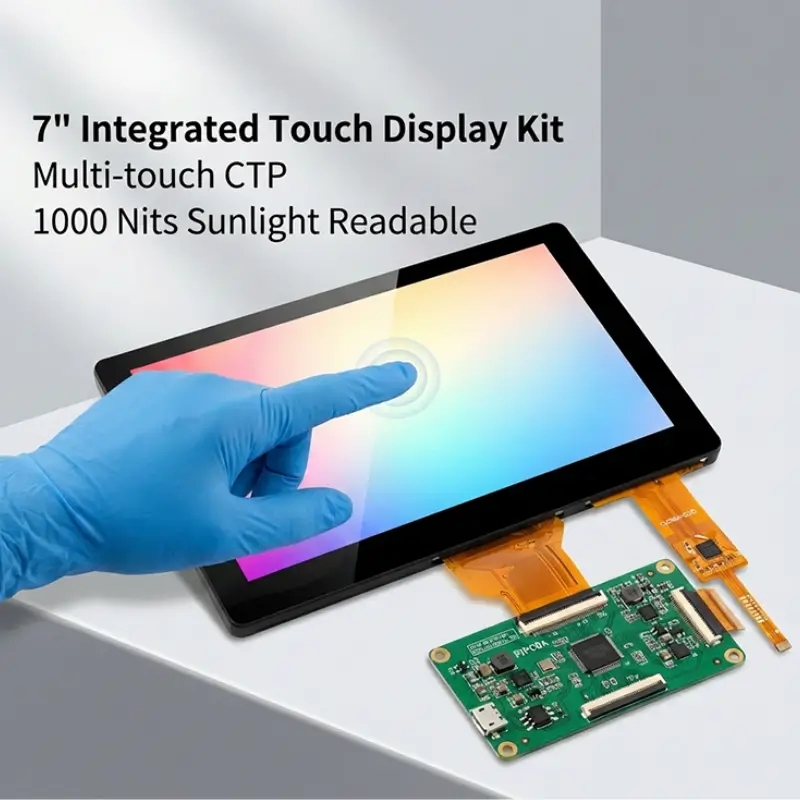
A TFT LCD with capacitive touch combines a thin-film-transistor liquid crystal display with a projected capacitive touch panel, commonly abbreviated as PCAP or CTP.
The TFT LCD creates the image. The capacitive touch sensor detects changes in an electric field when a finger or another suitable conductive object approaches the surface. A touch controller processes those changes and reports position data to the host processor.
The resulting assembly may include:
- A TFT LCD module and backlight
- A projected capacitive touch sensor
- A touch-controller IC and firmware
- Optical adhesive or perimeter tape
- A custom cover lens
- Separate display and touch FPCs or connectors
- An optional driver or interface board
These layers should be specified together. For example, increasing cover-glass thickness weakens the touch signal. Adding a printed border changes the sensor surroundings. Changing the display clock or power supply can alter electrical noise. Replacing air bonding with optical bonding changes the optical and mechanical stack.
Common PCAP Sensor Structures
Industrial PCAP panels are available in several constructions. Common examples include glass-glass, glass-film and glass-film-film, often written as G+G, G+F and G+FF.
G+G uses glass for the cover and sensor substrate. It is often selected for dimensional stability, surface durability and a robust front interface.
G+F and G+FF use one or more film sensor layers behind the cover lens. These structures can support thin or lightweight designs and may provide more flexibility for certain shapes and constructions.
No structure is automatically best for every product. The decision should consider thickness, optical performance, bezel design, impact requirements, sensor size, tooling and expected volume.
Start with the Operator, Not the Touch Technology
Before comparing PCAP and resistive touch, document how the operator will use the equipment.
Ask practical questions:
- Will the operator use a bare finger, medical glove, work glove or insulated winter glove?
- Is a passive stylus required?
- Does the interface require multi-touch, pinch or rotation gestures?
- How large are the buttons and touch targets?
- Is the device fixed, handheld or vehicle-mounted?
- Will the operator touch the screen while the equipment vibrates?
- Should the system accept input when wet, or only reject false touches?
- What must happen if water remains on the surface?
These questions often determine the correct technology more reliably than a generic preference for capacitive touch.
PCAP Touchscreen vs. Resistive Touchscreen
Both technologies can work in industrial equipment, but they respond to input differently.
How PCAP Touch Works
Projected capacitive touch measures changes in capacitance across a patterned sensor. It supports a sealed glass front, high optical clarity and multi-touch operation. With the correct controller, sensor and tuning, it may also support specified gloves and wet conditions.
PCAP is widely used in industrial HMIs, medical equipment, vehicle controls, smart-home panels and handheld instruments where appearance, gestures and long front-surface life are important.
How Resistive Touch Works
A resistive touchscreen detects physical pressure that brings conductive layers into contact. It can normally be operated with a finger, most gloves or a passive stylus.
Resistive touch remains useful for equipment with simple interfaces, single-point input or demanding glove and stylus workflows. It does not normally provide the same multi-touch experience or glass-front appearance as PCAP.
PCAP and Resistive Touch Comparison
| Selection factor | PCAP touchscreen | Resistive touchscreen |
|---|---|---|
| Input method | Finger and supported gloves; active stylus options depend on the controller | Finger, most gloves and passive stylus |
| Multi-touch | Supported by suitable controllers | Normally single touch |
| Front surface | Durable cover glass can form the user surface | Flexible top layer is typical |
| Optical appearance | High clarity is achievable | Additional layers may reduce clarity |
| Gesture support | Suitable for swipe, pinch and multi-finger gestures | Best for simple press-and-drag control |
| Wet operation | Requires defined water handling and tuning | Pressure input may be less sensitive to capacitive effects, but sealing is still required |
| Controller interface | Commonly I²C or USB | Commonly 4-wire or 5-wire analog input |
| Customization | Sensor, cover lens, printing, controller and firmware | Outline, tail, connector and overlay options |
| Best fit | Modern industrial HMI and sealed glass-front products | Stylus-led or universal-glove applications |
The right choice follows the workflow. PCAP is not automatically more industrial, and resistive touch is not automatically obsolete.
Touch Sensitivity with Gloves
A bare finger produces a stronger capacitive signal than a finger separated from the sensor by a glove and cover glass. To support gloves, the sensor and controller must detect a smaller change without becoming overly sensitive to noise or moisture.
“Glove operation” should be specified using the actual glove type. A thin nitrile examination glove, coated assembly glove, leather work glove and insulated winter glove present very different electrical and mechanical conditions.
Include these details in the touch specification:
- Glove manufacturer and part number, if available
- Glove material and thickness
- Whether the glove is dry, damp, contaminated or worn over another glove
- Minimum required touch-target size
- Required actions such as tap, drag, long press and gesture
- Maximum cover-glass thickness
- Acceptable response time and missed-touch rate
Supply production-intent glove samples during development. A touch panel tuned for one glove cannot be assumed to support every glove.
Does Thick Cover Glass Reduce Touch Sensitivity?
Yes. Increasing the distance between the operator and the sensor reduces capacitive coupling. Glass composition, adhesive thickness, printed ink, air gaps and nearby metal can also affect the signal.
It may be possible to operate through several millimeters of cover glass, but a thickness value alone cannot confirm performance. The final sensor pattern, controller, firmware, grounding and enclosure must be evaluated together.
Touch Operation with Wet Hands and Water
Water is conductive enough to disturb a capacitive field. Droplets can resemble touches, connect multiple sensor channels or interfere with a valid finger input.
An industrial PCAP controller may use water-rejection algorithms to distinguish between a finger and moisture. Depending on the design, the touchscreen may continue to accept a single-finger touch, limit gestures or temporarily reject all input when the surface is heavily wet.
The safest response depends on the product. A consumer appliance may prioritize continued operation. A machine control may prioritize preventing an unintended command.
Define the exact water condition:
- Scattered rain droplets
- A wet finger on a dry screen
- Cleaning spray
- Flowing water
- Condensation near the edge
- Salt water or conductive process fluid
- A fully flooded surface
Also define the expected system response. “No ghost touches during rain” is different from “full touch operation under running water.”
Water handling does not make a display waterproof. Ingress protection depends on the cover lens, adhesive, gasket, housing, cable exits and complete enclosure design.
Cover Glass, Surface Treatment and Durability
The cover lens is the part users see and touch, but it also affects optics, sensing and mechanical integration.
Cover-Glass Decisions to Specify
A custom cover lens may define:
- Outer dimensions and thickness
- Rectangular, rounded or irregular shape
- Edge finish and corner radius
- Viewing window and black-mask dimensions
- Logo and icon printing
- Transparent touch keys or indicator windows
- Holes, slots and mounting features
- Adhesive border and sealing area
- AR, AG or AF surface treatment
The black mask must hide the adhesive, sensor traces and display structure without clipping the active area. Tight alignment tolerances should be agreed across the TFT LCD, touch sensor, printing and housing.
AR, AG and AF Are Different Treatments
AR, or anti-reflection treatment, reduces mirror-like reflections. It is useful when strong lighting or outdoor use makes the cover behave like a mirror.
AG, or anti-glare treatment, diffuses reflected light. It can reduce distracting glare, but excessive haze may soften text and create sparkle over small pixels.
AF, or anti-fingerprint treatment, reduces the visibility of fingerprints and can improve cleanability and touch feel. Its abrasion life and compatibility with cleaning chemicals should be checked for the intended environment.
These treatments should be selected from real optical and maintenance requirements. Adding every available coating does not guarantee a better display.
What Does “Rugged Touch Screen” Mean?
“Rugged” is not a complete engineering specification. Translate it into product-level requirements such as:
- Impact energy and test method
- Surface hardness and abrasion test
- Chemical resistance and cleaning cycle
- Operating and storage temperature
- Vibration and mechanical shock
- UV exposure
- Ingress-protection target
- Expected field life
A strong cover lens alone does not certify a finished product to an IK or IP rating. Those ratings apply to the tested enclosure and assembly.
Air Bonding vs. Optical Bonding
Perimeter bonding attaches the touch panel around its edges and leaves an air gap above the TFT LCD. It is economical and can simplify rework, but the internal optical boundaries produce reflections.
Optical bonding fills the gap with a transparent adhesive. This can reduce internal reflection, improve perceived contrast and provide a more integrated appearance. It can also remove the cavity in which condensation might otherwise form.
Optical bonding is particularly useful when the industrial touchscreen display is used outdoors, viewed under strong lighting or expected to deliver premium optical quality.
The decision should also consider cost, repair strategy, bonding yield, cover size, temperature range and the risk of visible mura or bubbles. Once optically bonded, replacing one layer independently is generally impractical.
Choosing Touch Interfaces for Industrial HMIs
A TFT LCD with capacitive touch normally has two separate electronic interfaces. The display interface carries image data. The touch interface carries coordinate and gesture data. They should not be confused.
Common TFT LCD Interfaces
Small-size TFT LCD modules may use SPI, MCU, RGB or MIPI DSI, depending on resolution, refresh rate and processor platform. Larger or integrated HMI displays may also use LVDS, eDP, HDMI or another converted interface.
Choose the display interface by checking:
- Native interface supported by the host processor
- Required resolution, color depth and frame rate
- Available GPIO count and PCB routing space
- Cable length and EMI constraints
- Driver availability and software effort
- Power-up sequence and backlight control
I²C for Capacitive Touch
I²C is common for embedded PCAP controllers. It uses few signal lines and connects directly to many microcontrollers and application processors.
Confirm the controller address, interrupt line, reset line, voltage level, maximum bus length, Linux or RTOS driver support and firmware-update method. Long cables or electrically noisy equipment may require careful routing and validation.
USB for Capacitive Touch
USB touch is useful when the host is a PC-class platform, embedded Linux computer or industrial controller that supports USB Human Interface Device operation.
It can reduce driver-development effort when standard HID behavior is available. The trade-offs may include connector size, cable routing, power architecture and boot-time behavior.
Do Not Choose the Interface in Isolation
The correct interface is the one supported across the full product lifecycle. Check development tools, operating-system support, controller availability, firmware ownership and the process for future tuning updates.
Record the approved touch-controller firmware with the display assembly part number. A replacement controller or revised tuning file can change glove, water and edge-touch performance even when the mechanical drawing remains unchanged.
Electrical Noise and Grounding
Motors, inverters, switching regulators, chargers and radios can interfere with projected capacitive sensing. Raising touch sensitivity for gloves or thick glass may reduce noise margin.
Plan the hardware before relying on software filtering:
- Use a clean and stable touch-controller power supply
- Keep sensor and FPC routing away from switching nodes
- Define grounding between the display, touch controller, chassis and host
- Review shield design and termination
- Check metal features close to the sensor edge
- Test with the backlight at maximum brightness
- Test while motors, radios and chargers operate
A quiet evaluation board on a laboratory bench does not reproduce the final HMI. Final tuning should take place in the production-intent enclosure with the real power system and operating equipment active.
A Step-by-Step Selection Process
Step 1: Freeze the Viewing Requirement
Define active area, resolution, orientation, brightness, viewing angle and viewing distance. Confirm whether the display will be read indoors, outdoors or through polarized sunglasses.
Step 2: Describe the Operator
Identify finger, glove and stylus use. Define the required gestures and minimum touch-target size. Provide representative gloves rather than a general description.
Step 3: Describe the Environment
List temperature, moisture, cleaning agents, vibration, nearby electrical equipment and the required enclosure rating.
Step 4: Design the Cover Lens
Specify dimensions, thickness, shape, printing, edge finish, treatments and bonding area. Coordinate the viewing window and touch active area with the housing.
Step 5: Select the Display and Touch Interfaces
Match the TFT bandwidth and touch communication method to the host hardware and software. Confirm driver support, voltage levels, connectors and cable length.
Step 6: Choose the Bonding Method
Use the actual optical, environmental, cost and service requirements to compare air bonding and optical bonding.
Step 7: Build and Tune the Complete Assembly
Tune PCAP sensitivity after the display, cover lens, bonding, grounding, enclosure and power system are representative of production.
Step 8: Validate the Operator Workflow
Test complete tasks, not only isolated touch points. An operator should be able to select controls, drag values, dismiss alarms and navigate the HMI under the expected glove, water, temperature and vibration conditions.
Industrial Touchscreen Validation Matrix
| Test condition | What to verify |
|---|---|
| Bare dry finger | Accuracy, latency, edge response and gestures |
| Each specified glove | Tap, drag, long press and missed touches |
| Wet finger | Defined touch behavior and recovery |
| Water droplets | No unsafe false activation |
| Maximum cover thickness | Sensitivity margin and edge performance |
| Minimum and maximum temperature | Startup, tracking and recalibration |
| Motor or inverter operating | No ghost touches or controller lockup |
| Charger and communications active | Stable input in every power mode |
| Production cleaning chemical | Coating durability and reliable operation |
| Vibration or vehicle motion | Usable targets and no accidental input |
Acceptance criteria should be written before testing. “Touch works” is not measurable. Define allowable position error, missed-touch rate, false-touch behavior, response time and recovery after water or noise exposure.
Recommended Applications
Industrial Automation and Machine Controls
A PCAP TFT display can provide a sealed, easy-to-clean operator surface for compact machine controls, diagnostic panels and production equipment. Large touch targets and controlled false-touch behavior are important around moving machinery.
Medical and Laboratory Equipment
Medical and laboratory interfaces often prioritize cleanability, glove use, optical clarity and consistent touch response. The cover treatment and bonding materials should be checked against the intended disinfectants and cleaning cycles.
Vehicle and Transportation Displays
Vehicle-mounted displays may experience sunlight, vibration, electrical noise and large temperature changes. Glove use, polarized sunglasses, connector retention and display readability should be evaluated together.
Handheld Test and Measurement Instruments
Small TFT LCDs with capacitive touch can support compact graphical interfaces in portable meters and field instruments. Battery life, wet operation and one-handed use may influence the display size and UI design.
Smart Home and Building Controls
Wall-mounted controllers benefit from a clean glass front, custom printing and intuitive gestures. The designer should still check standby power, mounting-ground effects and long-term controller availability.
What to Include in an RFQ
Provide the following information when requesting a custom TFT LCD with capacitive touch:
- TFT LCD size, resolution and preferred viewing direction
- Required brightness and lighting environment
- Display interface and host processor
- Touch technology and number of touch points
- I²C or USB touch interface preference
- Required operating system or driver support
- Glove type and thickness
- Water condition and required behavior
- Cover-lens drawing, thickness and material
- Printing, logo and surface-treatment requirements
- Optical or perimeter bonding preference
- Operating and storage temperatures
- Mechanical shock, vibration, IP or IK targets
- Expected annual quantity and project lifetime
- Prototype schedule and validation requirements
Photos of the enclosure, a mechanical drawing and details of the host electronics allow a supplier to identify risks earlier.
How QIHAN Supports Custom TFT and Touch Projects
QIHAN manufactures and supplies small and medium-sized TFT LCD modules for industrial, medical, HMI, transportation and embedded applications.
QIHAN’s published touch capabilities include projected capacitive and resistive touch options. Standard PCAP offerings include G+G, G+F and G+FF structures, with I²C and USB interface options depending on the selected design.
Project-based customization can include TFT size and resolution, capacitive touch sensing, cover-glass dimensions and printing, FPC and connector design, interface selection, surface treatment and optical bonding.
Exact glove performance, cover thickness, controller selection and environmental capability must be reviewed for the individual project. They should not be inferred from the touchscreen technology alone.
Frequently Asked Questions
Can a PCAP touchscreen work with industrial gloves?
Yes, a properly selected and tuned PCAP system can support specified gloves. Performance depends on glove material and thickness, cover glass, sensor design, controller settings, touch-target size and electrical noise. Test the exact gloves used by operators.
Can a capacitive touchscreen work when wet?
It can be designed to reject water and may support defined wet-finger operation. The required behavior must distinguish droplets, cleaning spray, flowing water and a flooded surface. Wet-touch capability is separate from enclosure waterproofing.
Is PCAP better than resistive touch for an industrial HMI?
PCAP is often preferred for multi-touch, optical clarity and a durable glass front. Resistive touch may be better when any glove or a passive stylus must work without specialized tuning. The operator workflow should decide.
Should I use I²C or USB for the touch interface?
I²C is common for compact embedded systems and direct microcontroller integration. USB is convenient for PC-class and embedded Linux hosts that support HID devices. Select based on the host, cable length, software support and noise environment.
Does thicker cover glass make a touchscreen more rugged?
It may improve resistance to some mechanical loads, but thickness can reduce touch sensitivity and does not establish an enclosure rating. The complete product must be designed and tested against its impact, sealing and durability requirements.
Is optical bonding required for every industrial touchscreen?
No. Optical bonding is valuable when reflection, condensation risk or optical quality justifies it. Perimeter bonding may be adequate for controlled indoor environments or projects that prioritize cost and serviceability.
Can QIHAN customize the cover glass and touch interface?
Yes. QIHAN offers project-based cover-glass, touch-panel, FPC, interface and optical-bonding customization. Feasibility, tooling and order requirements depend on the selected display and mechanical design.
Select the Complete Touch System, Not a List of Components
An industrial TFT LCD with capacitive touch succeeds when the operator, optics, mechanics and electronics are designed together.
Start with real gloves, real water conditions and the actual HMI workflow. Specify the cover lens before touch tuning. Treat display and touch communication as separate interfaces. Validate the production-intent assembly with the equipment operating at its electrical and environmental limits.
QIHAN can help evaluate a small-size TFT LCD, PCAP or resistive touch panel, custom cover glass, bonding method and interface for your industrial application.