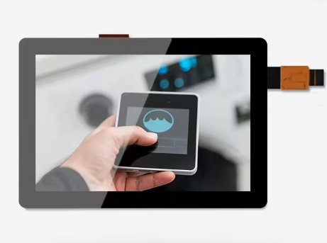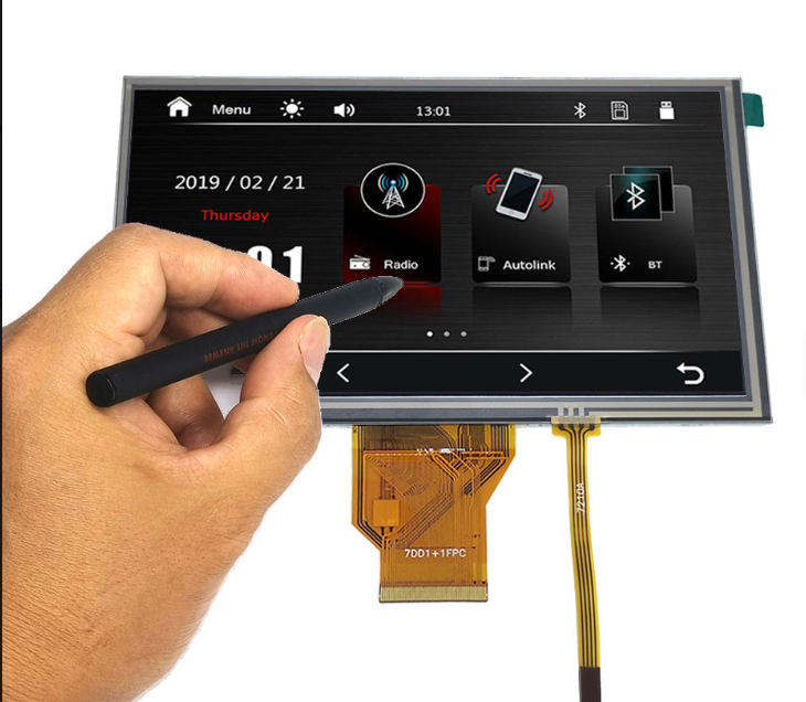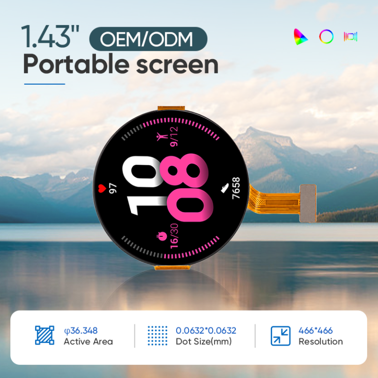
An industrial TFT LCD display should be selected from the operating task outward. Start with what the user must see and touch, then account for ambient light, temperature, moisture, vibration, electrical noise and service life.
This order matters because the specifications interact. More backlight output improves visibility but adds heat. Thicker cover glass can improve mechanical protection but weakens capacitive-touch coupling. Anti-glare treatment reduces sharp reflections but may soften small pixels. Optical bonding improves perceived contrast, yet changes cost, repair and process control.
The selection matrix in this guide compares four common applications: industrial control, medical equipment, vehicle HMIs and outdoor terminals. The values are engineering starting points, not universal pass/fail limits. Final requirements must be verified in the complete product.
Quick Selection Summary
- Indoor industrial control: Start around 400–700 nits, with AG treatment where overhead lighting causes glare. Prioritize long operating hours, EMI-resistant touch performance and practical mounting.
- Medical equipment: Start around 350–600 nits for general clinical interfaces. Define cleaning chemicals, glove use, gray-scale or color requirements and the role of the display before specifying coatings or bonding.
- Vehicle HMI: Start around 800–1,500 nits for sun-exposed cabin locations, while also requiring very low night brightness. Validate thermal load, vibration, viewing geometry and the exact mounting location.
- Outdoor terminal: Start around 1,000–2,500 nits depending on direct sun, reflection and viewing distance. Reduce reflection before increasing backlight power, and validate the sealed enclosure under solar load.
These ranges overlap. A sheltered outdoor controller may require less brightness than a machine HMI facing a sunlit window. The product environment—not the industry label—sets the final target.
1. Match Brightness to Ambient Light and Thermal Budget
Display luminance is measured in candelas per square meter, commonly called nits. It tells you how much light leaves the measured surface; it does not tell you how much contrast remains after ambient light is reflected by the cover glass and internal optical interfaces.
300–400 Nits: Controlled Indoor Conditions
This range can suit laboratory equipment, rack-mounted electronics and indoor terminals with controlled lighting and no direct sunlight.
At this level, review reflections from overhead lights and windows. A 350-nit display behind untreated glossy glass may be less comfortable than a similar display with a carefully selected surface treatment.
400–700 Nits: General Industrial Environments
This is a practical starting range for factory HMIs, handheld instruments and control panels under typical indoor lighting.
Brightness near the upper end can help where large doors, skylights or strong task lighting introduce more ambient light. It should not replace an assessment of glare, viewing angle and enclosure position.
700–1,000 Nits: Bright Indoor and Sheltered Outdoor Use
This range is often evaluated for equipment near windows, vehicle cabins, semi-outdoor terminals and devices used mainly in open shade.
AR or AG treatment and optical bonding can provide more value than increasing panel brightness alone. Confirm brightness through the finished touch and cover stack.
1,000–1,500 Nits: Regular Outdoor or Sun-Exposed Use
This range is a common engineering starting point for vehicle HMIs, EV chargers, field equipment and outdoor terminals that face strong daylight.
At this level, power and thermal management become central. Test the display after the sealed enclosure reaches its expected internal temperature, not only on an open bench.
1,500–2,500 Nits: Severe Direct-Sun Conditions
Very high brightness may be justified for continuous direct sun, long viewing distances, large optical losses or information that must be recognized immediately.
It is not automatically the best solution. A highly reflective 2,000-nit assembly may perform worse than a lower-brightness display with a well-designed bonded, low-reflection stack. Higher output also increases electrical load, heat and LED stress.
QIHAN publicly lists selected high-brightness solutions up to 1,800 nits. Requirements above that level should be treated as a project-specific feasibility question rather than an assumed standard capability.
Specify the Measurement Surface
Every brightness requirement should state one of the following:
- Bare TFT panel luminance
- Luminance through the touch panel
- Luminance at the outside of the completed cover lens
The final value is normally the most relevant to the user. Also specify whether the number is typical or minimum, together with uniformity, temperature and dimming conditions.
2. AR, AG and AF Surface Treatments
Surface treatments solve different problems and should not be combined by default.
AG: Anti-Glare
AG treatment diffuses reflected light so that a sharp lamp or window reflection becomes less distinct.
This can improve comfort in factories, vehicles and kiosks. Excessive haze may reduce apparent sharpness and create sparkle over small, high-density pixels. Evaluate AG with the real display resolution and interface graphics.
AR: Anti-Reflection
AR treatment reduces mirror-like reflection using an optical coating or surface structure.
It can preserve clarity better than a high-haze AG surface. Actual reflectance depends on wavelength, angle, substrate and the complete stack. Do not quote a sub-1% reflection target unless the supplier defines the measurement method and surface to which it applies.
AF: Anti-Fingerprint
AF treatment reduces visible fingerprints and can improve cleaning and touch feel.
It is useful for medical, vehicle and public touch interfaces. The treatment should be checked for abrasion life and compatibility with production cleaning agents.
A Practical Treatment Choice
| Main visual problem | Starting treatment | Verification |
|---|---|---|
| Sharp reflections of lamps, windows or sky | AR | Measure reflection and inspect at expected angles |
| Broad glare that causes operator discomfort | Balanced AG | Check haze, sparkle and fine-text clarity |
| Frequent finger contact and visible smudges | AF over a compatible surface | Test cleaning and abrasion cycle |
| Outdoor touch interface with several problems | Project-specific AR/AG/AF combination | Evaluate the finished stack, not separate material samples |
3. Perimeter Bonding vs. Optical Bonding
Perimeter or Air Bonding
Perimeter bonding attaches the touch panel or cover lens around its edges, leaving an air gap above the TFT.
Advantages can include lower cost, simpler processing and easier layer replacement. Limitations include additional internal reflections and a cavity in which moisture-laden air can condense.
It may be adequate for controlled indoor equipment when optical performance and condensation risk are acceptable.
Optical Bonding
Optical bonding fills the gap with a transparent OCA or OCR material. Reducing the refractive-index discontinuity can lower internal reflections and improve perceived contrast.
It also removes the internal air cavity and provides mechanical support between layers. It does not, by itself, make an enclosure waterproof or certify the assembly against impact.
Optical bonding is often valuable for:
- Sunlight-readable displays
- Large or dark cover lenses where reflection is visible
- Vehicle screens requiring an integrated black appearance
- Medical equipment exposed to frequent cleaning or splash risk
- Displays facing vibration or user pressure
It is not mandatory for every product in those categories. Cost, repair strategy, module size, bonding yield and application risk still matter.
Bonding Acceptance Criteria
Define limits for:
- Bubbles and particles
- Alignment and active-area position
- Edge defects and adhesive overflow
- Mura or pressure marks
- Yellowing or haze after aging
- Delamination after thermal and humidity exposure
- Optical uniformity
“Fully bonded” describes a process; it does not define quality.
4. Capacitive-Touch Response and Robustness
Projected capacitive touch, or PCAP, detects changes in an electric field. Touch response depends on the sensor pattern, controller, cover glass, adhesive, grounding, electrical noise and firmware.
Do Not Specify Response Time as One Number Too Early
The user experiences several delays:
- Sensor scan interval
- Controller filtering and touch confirmation
- Communication to the host
- Operating-system processing
- Application response
- Display-frame update
A fast controller cannot compensate for a slow application or display pipeline. Define an end-to-end interaction target for the real HMI task, then allocate the budget across the system.
For industrial controls, consistent response and rejection of unsafe false touches may matter more than the shortest possible reported latency.
Glove Operation
Thick cover glass and gloves both reduce capacitive coupling. Increasing sensitivity can recover the signal but may reduce tolerance to noise or water.
Specify the actual glove material, thickness and condition. A thin nitrile examination glove is different from a leather work glove or insulated winter glove.
Do not promise operation through 3–5 mm gloves or glass based on thickness alone. Validate the final sensor, controller, cover, enclosure and glove sample.
Water and Wet-Finger Behavior
Water can connect sensor channels and resemble a touch. A controller may reject droplets, accept a single wet finger, limit gestures or temporarily disable input on a flooded surface.
Define the intended behavior for rain, cleaning spray, condensation, wet fingers, flowing water and standing water. “Water tolerant” is incomplete without a test condition and expected response.
Electrical Noise
Motors, inverters, chargers, radios and switching power supplies can disturb PCAP sensing.
Frequency hopping and digital filtering may help, but hardware still matters. Review clean power, grounding, shielding, FPC routing, metal near the sensor and communication-cable length.
Final tuning should use the production-intent enclosure with the real equipment active at worst-case operating modes.
5. Cover Glass and Mechanical Durability
Cover-glass thickness is only one part of impact performance.
Chemical strengthening, material, edge quality, unsupported span, holes, mounting adhesive, enclosure stiffness and impact geometry all influence the result. A 6 mm cover can still fail if its edge is poorly supported; a thinner cover may perform well in a carefully designed assembly.
Surface-hardness values such as 6H, 7H or 9H refer to a defined test method and should not be treated as direct measures of impact resistance.
IP and IK Ratings Belong to Tested Assemblies
IEC 60529 classifies protection provided by electrical-equipment enclosures against access, solid objects and water.
IK ratings similarly apply to the tested enclosure’s resistance to external mechanical impact. A loose touch panel or cover lens cannot establish the complete equipment’s IP65, IP67 or IK10 rating.
If the product has an IP or IK target, coordinate:
- Cover-lens dimensions and unsupported area
- Gasket compression
- Bond width and adhesive
- Housing stiffness
- Cable and connector sealing
- Drainage or pressure equalization
- Test fixture and impact location
6. Application Requirements
Industrial Control and Factory HMI
The main risks are long operating hours, electrical noise, dust or oil, vibration and gloved operation.
Engineering starting points:
- Brightness: 400–700 nits indoors; higher near strong daylight
- Surface: AG where overhead lighting creates distracting reflections
- Bonding: perimeter or optical, based on reflection, condensation and service strategy
- Touch: test real work gloves; prioritize false-touch rejection around machinery
- Temperature: define from the cabinet and machine, not a generic industrial range
- Interface: RGB, LVDS, MIPI, MCU or another host-compatible option
- Durability: validate mounting, connector retention, FPC strain relief and EMI behavior
For 24/7 use, define the required luminance after the planned service interval and confirm the conditions behind the backlight-life value.
Medical Equipment
Medical products range from simple control panels to diagnostic image displays. They should not share one optical specification.
Engineering starting points:
- Brightness: approximately 350–600 nits for many general indoor interfaces; application-specific equipment may require more
- Surface: AR for clarity, AF for cleaning and controlled AG where glare justifies it
- Bonding: useful for optical clarity and eliminating the internal air cavity, but not universally mandatory
- Touch: test the specified nitrile, latex or other medical glove and each approved cleaner
- Sealing: design the complete front assembly for the required splash or ingress performance
- Color/gray scale: define according to the clinical task
- Interface: choose from host architecture and required image bandwidth
DICOM PS3.14 defines a standardized grayscale display function for consistent presentation. It does not prescribe one universal luminance range or automatically make a general medical control display suitable for diagnostic interpretation.
Vehicle HMI and Heavy Equipment
The main risks are solar load, day/night brightness range, temperature, vibration, electrical disturbances and changing viewing positions.
Engineering starting points:
- Brightness: approximately 800–1,500 nits for sun-exposed cabin locations
- Minimum brightness: define a low night value and smooth dimming behavior
- Surface: project-specific AR/AG/AF treatment
- Bonding: often valuable for reflection, black appearance and stack integration
- Touch: validate gloves, wet fingers, vibration and vehicle electrical noise
- Temperature: derive from the exact mounting location
- Viewing: confirm driver eye box, installation angle and polarized sunglasses
- Interface: RGB, MIPI, LVDS, eDP or a vehicle-system architecture selected by the integrator
ISO 16750 describes environmental stresses and tests by mounting location. Do not apply one dashboard test profile to every in-cabin, exterior or heavy-equipment installation.
Outdoor Terminals, EV Chargers and Kiosks
The main risks are direct sunlight, heat, rain, vandalism, UV exposure and continuous public operation.
Engineering starting points:
- Brightness: approximately 1,000–2,500 nits depending on reflection and sun exposure
- Optical design: prioritize reflection reduction and enclosure shading before maximum backlight power
- Surface: AR or balanced AR/AG, with AF where frequent touch is expected
- Bonding: commonly beneficial for sunlight readability and condensation control
- Touch: define safe behavior during rain and test the complete wet front surface
- Cover: select thickness and strengthening from product-level impact requirements
- Temperature: include solar load, sealed-enclosure heat and possible cold-start conditions
- Interface: LVDS, eDP, HDMI or another architecture appropriate to the host and cable route
UV-resistant materials may be required for the cover, adhesive, polarizer and printing. “UV cut” on one layer does not prove that the complete stack will avoid yellowing or degradation.
Industrial TFT LCD Application Selection Matrix
| Evaluation item | Industrial control HMI | Medical equipment | Vehicle HMI / heavy equipment | Outdoor terminal / EV charger |
|---|---|---|---|---|
| Typical environment | Indoor factory, cabinet or machine | Clinical, laboratory or mobile equipment | Cabin, vehicle body or mobile machinery | Exposed or sheltered outdoor installation |
| Brightness starting range | 400–700 nits | 350–600 nits; higher if the task requires it | 800–1,500 nits in sun-exposed positions | 1,000–2,500 nits according to direct sun and reflection |
| Most important optical metric | Readability under overhead lighting | Task-specific gray scale, color and cleanability | Day/night contrast across driver positions | Ambient contrast through finished cover stack |
| Surface-treatment starting point | AG; AR if sharp reflections dominate | AR/AF; controlled AG only when useful | Project-specific AR/AG/AF | AR or balanced AR/AG; AF for touch |
| Bonding choice | Perimeter or optical | Optical when optics, cleaning or condensation justify it | Often optical; confirm repair and thermal needs | Optical commonly preferred; validate aging |
| PCAP priority | Glove operation and EMI immunity | Medical-glove accuracy and cleaner compatibility | Stable touch under vibration, temperature and electrical noise | Water rejection, wet-finger behavior and vandal-resistant stack |
| Response requirement | Consistent task response; prevent unsafe false activation | Accurate selection and predictable gesture behavior | Stable day/night operation and driver-oriented UI response | Reliable public interaction despite rain and temperature |
| Cover-glass approach | Thickness set by enclosure and impact risk | Chemically compatible, cleanable and sealed | Strengthened and retained for vehicle vibration/impact requirement | Strengthened, supported and validated at product-level IK target |
| Temperature definition | Cabinet internal minimum and maximum | Product and transport conditions | Exact vehicle mounting location | Ambient plus solar and sealed-enclosure rise |
| Mechanical focus | Mounting stress, FPC strain and connector retention | Cleanable joints, dropped equipment and cart vibration | Resonance, shock, thermal expansion and cable retention | Impact, gasket, adhesive, enclosure stiffness and sealing |
| Interface starting point | MCU, RGB, MIPI or LVDS | LVDS, eDP, MIPI, RGB or host-specific | RGB, MIPI, LVDS, eDP or system-defined link | LVDS, eDP, HDMI or host-specific |
| Lifetime question | Brightness after continuous operating schedule | Performance after cleaning and intended service cycle | Optical/touch stability across vehicle program | Backlight and material aging under heat and UV |
| Must be verified | EMI, glove sample, mounting and 24/7 duty | Clinical role, cleaners, gloves and applicable standards | Customer specification, mounting location and system qualification | Finished-surface luminance, thermal behavior, rain, IP and IK assembly tests |
7. Backlight Life and Long-Term Use
Backlight lifetime is often expressed as hours until luminance falls to a defined percentage of its initial value. The percentage, drive current and temperature must be stated.
Do not convert a 50,000-hour or 100,000-hour marketing number directly into product life. Ask whether the value is typical, calculated or tested and whether it applies at maximum brightness.
Estimate the duty cycle:
Annual backlight hours = operating hours per day × operating days per year × backlight-on factor
Then define the minimum acceptable luminance at the end of the intended service period.
Automatic dimming, screen timeout and thermal derating may reduce stress. For outdoor terminals, verify backlight life under the actual internal temperature rather than room temperature.
8. Interfaces and Integration
The correct interface is determined by processor capability, resolution, frame rate, cable length and EMI environment.
Common choices include:
- MCU or SPI for compact, moderate-update displays
- RGB for direct pixel streaming
- MIPI DSI for high bandwidth with fewer signal lines
- LVDS or eDP for selected medium-size or remote displays
- HDMI through a driver board for PC-class hosts
The interface name alone is insufficient. Confirm timing, voltage, lane mapping, initialization, power sequence, frame-buffer requirements and connector pinout.
For PCAP, I²C is common in embedded systems and USB is convenient for HID-compatible hosts. Record the controller, firmware and tuning revision with the display assembly.
9. Engineering Decision Checklist
Step 1: Define the Visual Task
Record the smallest text, viewing distance, critical colors, image motion and whether the information is safety relevant.
Step 2: Measure the Light Environment
Classify controlled indoor, bright indoor, sheltered outdoor or direct sun. Identify sharp reflection sources and viewing angles.
Step 3: Set Brightness at the Correct Surface
State whether the requirement applies to the bare panel or completed cover surface. Include typical/minimum, uniformity, temperature and dimming.
Step 4: Select Reflection Control
Choose AR, AG and bonding from measured reflection, haze and clarity needs. Do not use brightness as the only outdoor solution.
Step 5: Define Touch Behavior
Provide real gloves, water conditions, required gestures and acceptable false-touch behavior. Set an end-to-end interaction target.
Step 6: Design the Mechanical Stack
Control support surfaces, screw torque, gasket compression, glass span, FPC routing and connector access.
Step 7: Define Environmental Evidence
Set temperature, humidity, vibration, shock, chemical, UV, IP and IK requirements for the complete product and mounting location.
Step 8: Confirm Lifecycle and Change Control
Share prototype, pilot and annual quantities. Request part-specific change notification, controlled drawings, approved firmware and an alternate strategy.
10. RFQ Information for QIHAN
For an efficient engineering review, provide:
- Application and installation location
- Required active area, resolution and orientation
- Maximum module envelope
- Lighting environment and cover-surface brightness target
- AR, AG, AF and bonding preferences
- Touch points, glove and water requirements
- Cover-lens drawing and impact target
- Operating and storage temperatures
- Vibration, shock, moisture, chemical and UV conditions
- Host processor, display interface and touch interface
- Power and thermal limits
- Prototype, pilot and annual quantities
- Target schedule and expected product lifetime
- Applicable customer, medical, vehicle or enclosure standards
Mark each parameter as fixed, preferred or open to recommendation.
How QIHAN Supports Small Industrial TFT LCD Projects
QIHAN manufactures and supplies small and medium-sized TFT LCD modules from 0.96 to 15.6 inches for industrial, medical, vehicle-related, outdoor and embedded applications.
QIHAN’s published capabilities include selected high-brightness configurations up to 1,800 nits, wide-temperature and transflective TFT options, PCAP and resistive touch, custom cover glass, AR/AG/AF treatments, optical bonding, FPC and interface customization, and driver-board development.
The company also publishes high- and low-temperature, vibration, backlight, CTP and optical-bonding production or test resources.
Availability and performance depend on the exact module and construction. Brightness above QIHAN’s published range, thick-glove performance, sub-1% reflection, particular IP/IK targets or fixed lifetime figures require project-specific evaluation and should not be assumed.
Frequently Asked Questions
Is 1,000 nits enough for sunlight readability?
Sometimes, but not always. Finished-surface reflection, optical bonding, viewing angle, UI contrast and direct-sun exposure affect the result. Test a production-intent stack outdoors.
Does optical bonding eliminate all reflection?
No. It reduces internal reflection by removing the air gap. The outer cover surface and other optical layers still reflect light.
Is optical bonding mandatory for medical equipment?
No universal rule makes it mandatory for every medical display. It may be valuable for clarity, cleanability and condensation control. The product’s clinical role, risk process and applicable standards determine the requirement.
Can a capacitive touchscreen work through 6 mm glass?
It may be possible with a suitable sensor, controller and tuning. Performance depends on glass, adhesive, printed ink, touch size, grounding and electrical noise. Validate the exact stack.
Does 7H cover glass provide an IK rating?
No. Pencil hardness and external-impact resistance are different tests. An IK rating applies to the tested enclosure assembly, not to the cover glass alone.
Does optical bonding make the product IP65 or IP67?
No. IP protection depends on the complete enclosure, including the cover, gasket, housing, seams and cable exits.
Does DICOM compliance require at least 1,000:1 contrast?
DICOM PS3.14 defines a standardized grayscale display function; it does not prescribe one universal display luminance or contrast ratio. The clinical application and product requirements determine the necessary performance.
What is a realistic TFT backlight life?
It depends on LED current, temperature, duty cycle and the defined luminance endpoint. Request conditions for the exact module rather than relying on a generic hour value.
Optimize the Complete Stack, Not One Specification
The best industrial TFT LCD decision is rarely the highest-brightness or thickest-glass option.
Reduce reflection before adding unnecessary backlight power. Select surface treatment with the real pixels and lighting. Tune PCAP behind the final cover glass. Define impact and sealing at enclosure level. Calculate lifetime from actual duty and temperature.
QIHAN can review your application, mechanical envelope, brightness target, touch conditions, interface and environmental requirements to propose a standard or customized small industrial TFT LCD assembly.